Slow cooling, low suction pressure and unstable refrigerant flow often lead technicians to suspect the thermostatic expansion valve. However, these symptoms don’t always indicate a faulty TXV or justify an adjustment.
Before adjusting the valve, verify your measurements, evaporator load and liquid supply. This guide explains TXV operation, superheat measurement and practical troubleshooting for direct-expansion cold rooms and air-conditioning systems.
Notice: Only qualified technicians should service pressurized refrigeration systems, electrical equipment and refrigerants. Follow the equipment and valve manufacturers’ instructions and operating limits.
What Does Thermostatic Expansion Valve Do?
A thermostatic expansion valve, or TXV/TEV, meters refrigerant into the evaporator. It performs two main functions:
| Function | Purpose |
|---|---|
| Throttling | Reduces refrigerant pressure and delivers a low-pressure liquid–vapor mixture to the evaporator |
| Flow regulation | Adjusts refrigerant flow in response to evaporator outlet superheat |
Proper flow control helps the evaporator use its heat-transfer surface effectively and reduces the risk of liquid refrigerant returning to the compressor. However, TXV doesn’t replace other floodback protection measures.
A TXV regulates evaporator outlet superheat—not room temperature directly. Opening the valve further doesn’t necessarily improve cooling.

How Does TXV Work?
TXV uses sensing bulb, capillary tube, diaphragm, spring and valve needle.
The sensing bulb tracks the suction-line temperature near the evaporator outlet. Its internal charge develops pressure and transmits that pressure through the capillary tube to the diaphragm.

3 main forces control valve movement:
| Input | Main effect |
|---|---|
| Sensing bulb pressure | Pushes the valve toward opening |
| Equalizer pressure | Pushes the valve toward closing |
| Spring force | Pushes the valve toward closing and influences the superheat setting |
Within its intended operating range, the TXV increases refrigerant flow as outlet superheat rises and reduces flow as superheat falls.
This control process remains dynamic. Changes in load, liquid supply and operating conditions can affect pressure, temperature and valve response.
Internally vs. Externally Equalized TXVs
The main difference concerns the pressure source that acts beneath the diaphragm.
| Type | Pressure source | Application consideration |
|---|---|---|
| Internally equalized | Valve outlet, through an internal passage | Suitable where the evaporator pressure drop remains within the manufacturer’s limit |
| Externally equalized | Near the evaporator outlet, through an external line | Accounts for pressure drop through the evaporator and distributor |
A significant pressure drop creates a difference between valve outlet pressure and evaporator outlet pressure. Follow the equipment manufacturer’s requirements when choosing the equalization method.
The external equalizer provides essential pressure feedback. Never cap it or omit its connection.
How to Measure and Calculate Superheat?
Superheat measures how far refrigerant vapor temperature exceeds its saturation temperature at the same pressure.
Evaporator outlet superheat = outlet vapor temperature − saturation temperature at outlet pressure
In field measurements, a firmly attached and insulated temperature probe uses suction-pipe surface temperature to approximate refrigerant vapor temperature.
Don’t substitute evaporator discharge-air temperature or room temperature for suction-line temperature. Match the temperature measurement with the pressure at that location.

Superheat Calculation Example
The following example illustrates the calculation only. It does not represent a field case or a recommended setting.
Assume the correct refrigerant pressure–temperature data gives these values:
| Measurement | Example |
|---|---|
| Saturation temperature at evaporator outlet pressure | −10°C |
| Suction-line temperature at the same location | −4°C |
| Calculated superheat | 6 K |
Superheat = −4 − (−10) = 6 K
A temperature difference of 6 K equals a difference of 6°C. However, a 6 K reading alone doesn’t prove correct operation. Compare the result with the equipment manufacturer’s target range and test conditions.
Dew Point vs. Bubble Point
For refrigerant blends with temperature glide, pressure–temperature charts may show both dew-point and bubble-point values.
| Calculation | Temperature reference |
|---|---|
| Vapor superheat | Dew point |
| Liquid subcooling | Bubble point |
Don’t use bubble-point or mean evaporating temperature to calculate vapor superheat.
Evaporator Outlet vs. Compressor Inlet Superheat
These measurements serve different purposes:
| Measurement location | Main purpose |
|---|---|
| Evaporator outlet | Evaluate TXV superheat control |
| Compressor inlet | Check compressor suction conditions |
The suction line can absorb heat and introduce pressure loss between these locations.
If you measure pressure only at the compressor, assess the suction-line pressure drop before combining that reading with the evaporator outlet temperature.
What to Check Before Adjusting a TXV?
Abnormal superheat starts the investigation. It doesn’t automatically justify turning the adjustment stem.
1.Verify Measurement Accuracy
Confirm the following:
- Correct refrigerant selection in the gauge or pressure–temperature tool
- Consistent pressure units and gauge/absolute pressure settings
- Firm temperature-probe contact and protection from ambient heat
- Matching pressure and temperature measurement locations
- Readings from the same operating period
A digital tool can simplify calculations, but it can’t correct the wrong refrigerant selection or measurement location.
2.Check Evaporator Heat Transfer
Inspect the fans, coil cleanliness, frost buildup and airflow path. For air-conditioning systems, also check filters and actual airflow.
Correct airflow and heat-transfer problems before adjusting the valve. TXV adjustment can’t compensate for a blocked coil or failed fan.
3.Check Liquid Supply
Inspect refrigerant charge and liquid supply conditions, liquid-line subcooling, and possible restrictions in the filter-drier, valves or piping.
TXV needs adequate liquid refrigerant at its inlet. Changing its superheat setting can’t correct an upstream supply problem.
4.Check the Sensing Bulb and Equalizer
Confirm proper bulb contact, secure mounting, insulation and protection from external heat sources. Check the external equalizer connection and look for damage or restrictions.
Follow the specific valve model’s installation requirements. Correct feedback problems before judging the valve setting.
Notice: For bulb mounting, equalizer routing and prestart checks, follow our cold-room TXV installation and commissioning guide.
5.Identify the Operating Stage
Record whether the system has just started, is pulling down temperature, is approaching setpoint or is recovering from defrost.
Don’t compare readings from different operating stages as though they represent the same load. Avoid repeated adjustments based on a single snapshot.
Use a consistent field record:
| Record | Details |
|---|---|
| Equipment | Refrigerant, TXV model and evaporator model |
| Operating conditions | Time, room temperature and operating stage |
| Measurements | Test locations, pressure, pipe temperature and superheat |
| Observations | Cooling performance, frost condition and fault symptoms |
| Changes | Adjustment direction, amount and follow-up readings |
How to Adjust TXV Superheat?
Step 1: Confirm Adjustability
Not every TXV allows field adjustment.
Check the model documentation for the adjustment method, access point and permitted range.
Different valve series can have different sensitivities per turn. Don’t copy the adjustment amount from another model.
Step 2: Establish the Correct Target
Don’t apply one universal superheat setting to cold rooms, low-temperature freezers and air conditioners.
Check:
- Equipment manufacturer’s target and measurement location
- Valve’s application range
- Compressor’s suction-condition limits
- Load conditions for testing.
Also distinguish static superheat from operating superheat. The valve’s static setting doesn’t necessarily equal the superheat you should measure under load.
Step 3: Make Small, Model-Specific Adjustments
Many adjustable TXVs use the following directions:
| Direction | Typical setting change |
|---|---|
| Clockwise | Increases superheat setting |
| Counterclockwise | Decreases superheat setting |
Confirm the direction and adjustment increment in the valve manual.
These directions describe the setting change—not a guaranteed operating response. Other system faults may prevent the expected result.
Step 4: Allow the System to Stabilize
Record each adjustment and allow the system to rebalance before making another change.
A 10–15-minute observation period provides a useful starting point for many applications, but follow the equipment instructions and actual operating response. Elapsed time alone does not prove stability.
If repeated adjustments produce no reasonable response, stop turning the stem. Recheck liquid supply, sensing-bulb feedback, equalizer condition, restrictions and valve compatibility.
Step 5: Verify Overall Performance
Don’t finish commissioning based on one acceptable superheat reading.
Confirm that:
- Pressure and temperature trends stabilize
- Cooling performance meets the application requirements
- The system shows no signs of floodback or compressor protection trips
- The valve maintains acceptable control as the load changes
If abnormal operation continues, stop further trial adjustments and follow the equipment troubleshooting procedure.
TXV Adjustment Case Study: Before-and-After Results
System and Cooling Problem
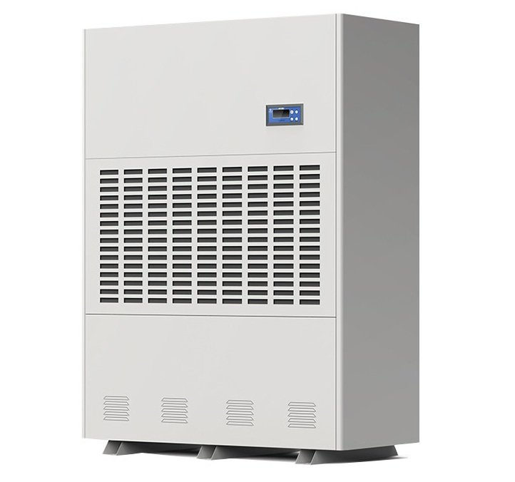
A constant-temperature-and-humidity air-conditioning unit showed poor cooling performance while both compressors operated. The investigation focused on evaporator outlet superheat and TXV operation.
Refrigerant: R410a
Inspection and Diagnosis
Initial checks indicated adequate refrigerant charge and no filter blockage. Temperature and pressure measurements showed high evaporator outlet superheat, which suggested insufficient refrigerant flow relative to the evaporator load.
The technician reviewed these findings before adjusting the TXVs.
TXV Adjustment
The technician adjusted the TXVs to reduce excessive superheat, allowed the system to stabilize, and recorded follow-up temperature and pressure readings.
The assessment compared operating superheat before and after adjustment rather than relying on suction pressure alone.
Superheat Before and After Adjustment
The following table summarizes the measurements for both refrigeration circuits.
| Item | Evaporator outlet Temp (°C) | Compressor air outlet pressure (kg/cm2) | Ralated temp for Compressor air outlet pressure(°C) | Overheat(°C) | Overheat meet the request or not |
|---|---|---|---|---|---|
| Manufacturer's debug standard value | <14 | 4.5~6 | 2.5~11 | 5~8 | Yes |
| (#1 compressor) before debug | 21.0 | 3.2 | -5.0 | 26.0 | No |
| (#1 compressor) after debug | 12.3 | 5.0 | 5.8 | 6.5 | Yes |
| (#2 compressor) before debug | 20.5 | 4.0 | 0.0 | 20.5 | No |
| (#2 compressor) after debug | 13.9 | 5.2 | 6.0 | 7.9 | Yes |
After adjustment, outlet superheat decreased from 26.0 K to 6.5 K in Circuit 1 and from 20.5 K to 7.9 K in Circuit 2.
These results show lower outlet superheat in both circuits under the recorded test conditions.
Air-Temperature Comparison
The following chart compares the air temperatures before and after adjustment.
| Item | Air conditioning air outlet | Air conditioning air outlet | Air conditioning air inlet | Air conditioning air inlet | Temp gap between air inlet and outlet |
|---|---|---|---|---|---|
| Unit | Temp (°C) | Humidity (%) | Temp (°C) | Humidity (%) | (°C) |
| Before debug | 22.5 | 54.8 | 16.8 | 75.4 | 5.7 |
| After debug | 22.5 | 54.8 | 14.3 | 84.3 | 8.2 |
The temperature difference between the two air measurement points increased from 5.7 K to 8.2 K. The warmer point remained at 22.5°C, while the cooler point decreased from 16.8°C to 14.3°C.
Results and Application Limits
The recorded results show lower evaporator outlet superheat and a larger air-temperature difference after TXV adjustment.
However, these readings alone don’t quantify cooling-capacity gains or energy savings. Such conclusions require additional measurements, including airflow, humidity and power consumption under comparable conditions.
The final superheat values apply to this case only. Follow the equipment manufacturer’s requirements when evaluating other systems.
Common TXV Symptoms and Troubleshooting Checks
Use symptoms to guide inspection—not to identify a failed component on their own.
| Symptom | Possible causes | Priority checks |
|---|---|---|
| High superheat and poor cooling | Inadequate liquid supply, restriction, incorrect valve capacity or faulty feedback | Verify measurements; check liquid supply, filter-drier, bulb and equalizer |
| Low superheat | Excessive feeding, low load, poor airflow or bulb problems | Check load, fans, frost and bulb condition before adjusting |
| Fluctuating superheat and suction pressure | Hunting, changing load, incorrect valve sizing or installation problems | Log operating trends; check airflow, load, valve selection and bulb mounting |
| Low suction pressure after TXV replacement | Remaining restriction or incompatible valve/orifice | Confirm refrigerant compatibility, valve model, orifice and liquid-line condition |
| Little response to adjustment | Supply restriction, feedback failure, valve damage or operation outside the valve’s range | Recheck system conditions and follow the model-specific diagnostic procedure |
Notice: High superheat doesn’t automatically mean low refrigerant charge. Low suction pressure doesn’t automatically mean a failed TXV.
Always evaluate the wider system before replacing the valve.
If diagnosis confirms that you need a replacement, use our TXV manufacturer overview to explore brands, then verify the exact model and application with the supplier.
TXV Adjustment FAQs
Q1.Does Lower Superheat Always Improve Cooling?
No. Aim for stable operation within the equipment manufacturer’s limits, not the lowest possible reading.
Very low superheat can indicate overfeeding or a load problem and may increase floodback risk.
Q2.Does Every New TXV Need Adjustment?
No. First verify the valve model, installation, liquid supply and operating performance.
Adjust only when the readings justify a change and the valve permits field adjustment.
Q3.Can Suction Pressure Alone Confirm Correct TXV Operation?
No. Evaluate suction pressure alongside refrigerant type, suction-line temperature, load, airflow and liquid supply.
Q4.When Should You Replace a TXV?
First rule out measurement, installation, supply and load problems. Consider repair or replacement when model-specific checks confirm component damage or an unsuitable valve. Follow the manufacturer’s service recommendations.
What Information Should You Provide for Technical Support?
Complete field information helps your supplier distinguish valve faults from installation, supply and measurement problems.
| Information | What to provide |
|---|---|
| Valve identification | Nameplate photo, model and orifice identification |
| System details | Refrigerant, evaporator and condensing-unit models |
| Installation photos | Sensing bulb, equalizer connection and liquid piping |
| Operating conditions | Room temperature, operating stage and fault timing |
| Measurements | Pressure, pipe temperature and superheat, with test locations |
| Service history | Recent replacements, charging work and valve adjustments |
When requesting TXV, evaporator or refrigeration-accessory support from Speedway Refrigeration Group, include these details so our team can review the application and matching requirements.
Conclusion
Effective TXV troubleshooting starts with reliable measurements, correct feedback and adequate liquid supply—not a fixed number of adjustment turns.
Verify the readings, check system conditions, then decide whether to adjust, repair or replace the valve.
Keep before-and-after records to support commissioning, handover and future service.