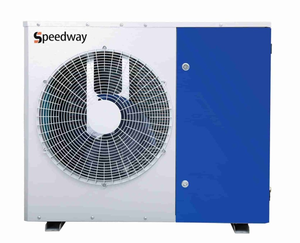
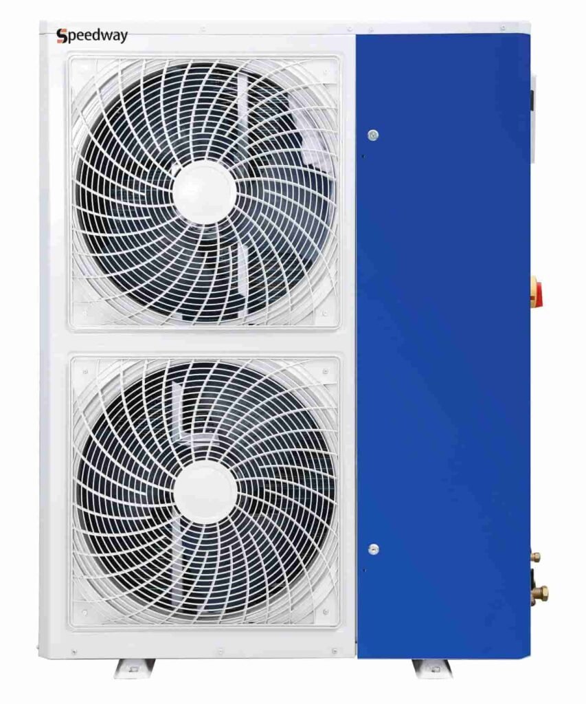
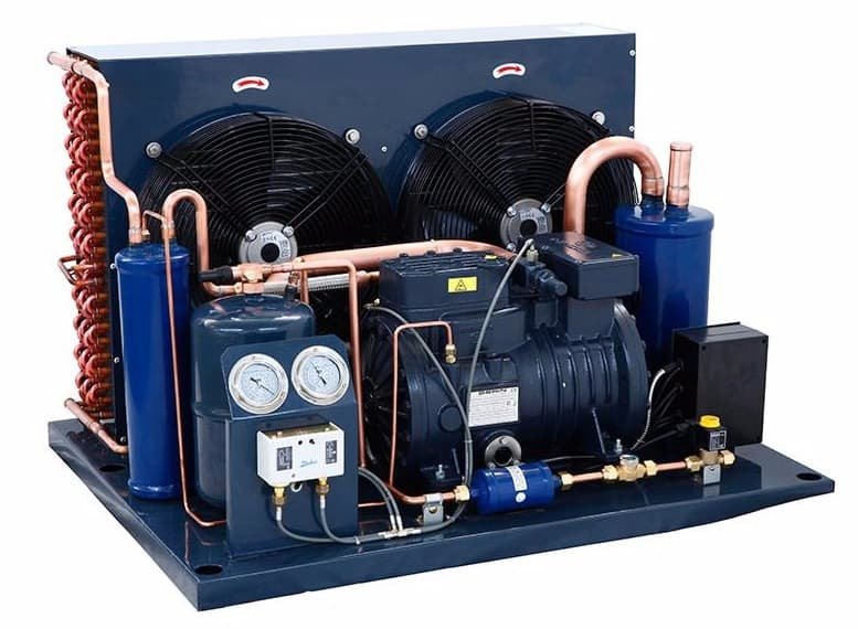
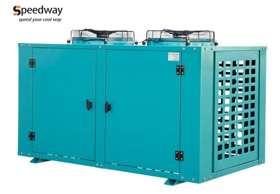
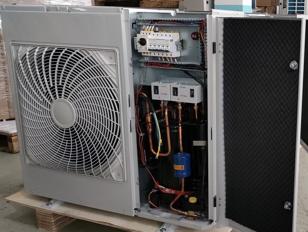
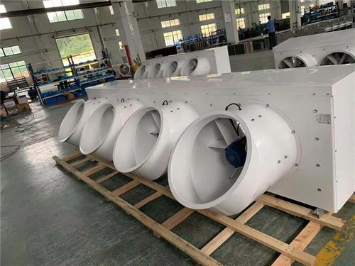
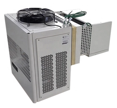
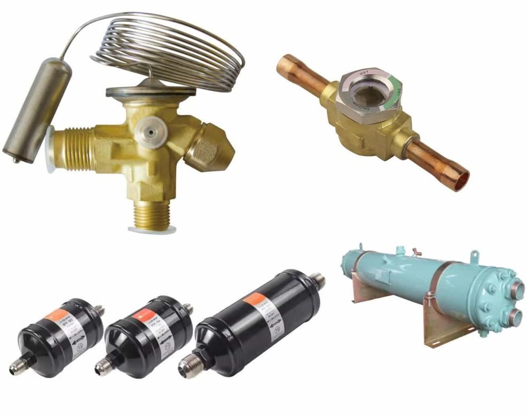
Using one condensing unit for multiple cold rooms means one outdoor condensing unit supplies refrigerant to two or more evaporators, usually one evaporator for each room, through a shared liquid line and a shared suction return.
This setup can lower equipment cost, save outdoor space, and simplify maintenance. However, it only works well when the room temperatures, load conditions, piping design, and control logic all match the application.
The key idea is simple: each cold room must cool independently.
One room should call for cooling, reach set temp, and stop cooling without forcing the other rooms to overcool or lose control.
When This Design Makes Sense
A one-condensing-unit multi-room design works best when the cold rooms have similar temperatures and similar operating conditions.
Good Applications:
| Project Type | Suitability | Why |
|---|---|---|
| Two or more chiller rooms | Good | Similar room temperatures make control easier |
| Two or more freezer rooms | Usually good | Same suction condition works better |
| Several small cold rooms in one facility | Good | Saves space and reduces equipment quantity |
| Projects with limited outdoor installation area | Good | One condensing unit needs less space |
Applications That Need Extra Care:
If all rooms stay close in temperature, one shared suction condition can often support the whole system. If one room runs as a freezer and another runs as a chiller, the design needs extra pressure control.
How the System Works
In this design, the condensing unit acts as the refrigeration source, and each cold room acts as an independent cooling zone.
Each room usually includes its own control and refrigerant feed components.
Basic Component Layout:
The thermostat in each room controls that room’s solenoid valve.
When the room temperature rises above setpoint, the thermostat opens the solenoid valve. Refrigerant then flows to that room’s evaporator. When the room reaches setpoint, the thermostat closes the solenoid valve and stops refrigerant flow to that room.
This setup gives each room independent on/off cooling control while all rooms share one condensing unit.
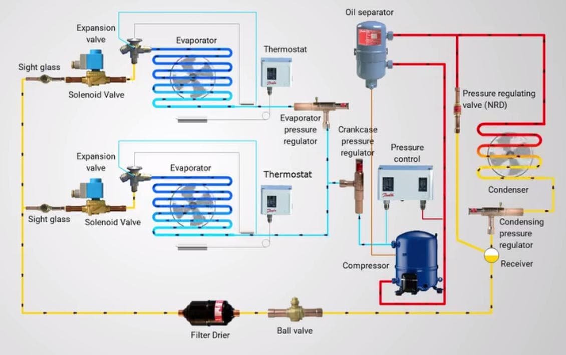
Multiple Cold Rooms Refrigeration Circuit
Same-Temperature Rooms: The Simplest Configuration
Same-temperature rooms create the simplest and most reliable one-to-many setup.
For example, if you have three cold rooms at +2°C, +3°C, and +4°C, one shared condensing unit often works well because the system can use a similar suction condition for all three rooms.
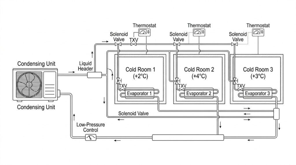
Same-Temperature System Layout:
Why This Layout Works Well:
In this type of project, the system usually controls well as long as the load calculations, piping, and component selection are correct.
Mixed-Temperature Rooms: Chiller and Freezer on One Unit
When one condensing unit serves a chiller and a freezer, the design becomes more difficult.
The reason is: the freezer needs a lower suction pressure.
If the chiller shares that same low suction condition directly, the chiller evaporator can run too cold. That can cause overcooling, coil icing, unstable room temperature, or even product freezing inside the chiller.
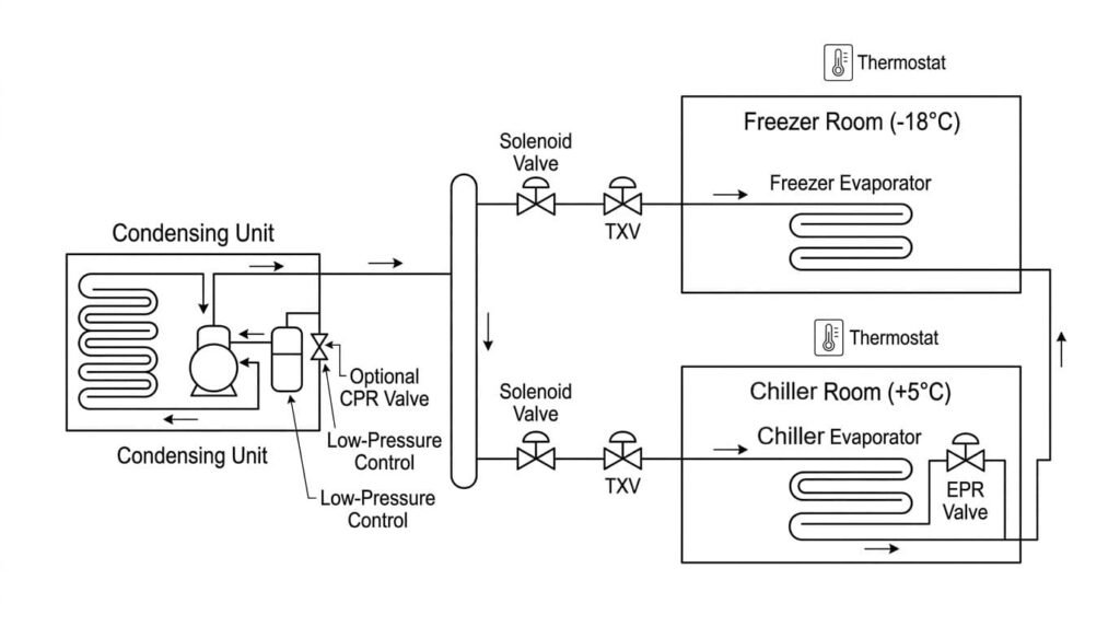
Example:
In this situation, a basic shared system usually doesn’t perform well by itself.
The chiller room branch often needs an EPR valve.
What an EPR Valve Does
An EPR valve helps the warmer room keep a higher evaporator pressure.
You usually install the EPR valve in the suction line of the warmer room, after the evaporator and before the common suction header.
EPR Valve Logic:
With this arrangement:
-
The freezer branch follows the lower suction condition it needs.
-
The chiller branch stays at a higher evaporator pressure because the EPR valve holds it there.
That is how one condensing unit can serve two different temperature rooms more safely.
When Does a Branch Need an EPR?
Don’t decide from room temperature difference alone.
Compare the branch’s required evaporating pressure with the common suction pressure. If the branch needs a higher evaporating pressure, assess an EPR or another suitable control arrangement.
Check refrigerant, branch capacity, available pressure drop and the valve’s operating range. The room controller still controls room temperature; the EPR controls evaporator pressure.
When a CPR Valve May Help
Some projects also need a CPR valve near the compressor suction.
A CPR valve protects the compressor during startup or hot pull-down. If several rooms call for cooling at the same time, or if warm product enters the rooms, suction pressure can rise quickly. That high suction pressure can overload the compressor.
CPR Valve Logic:
| Question | Answer |
|---|---|
| Why use a CPR valve? | Protect compressor during heavy load conditions |
| Where do you install it? | Near the compressor suction |
| When is it useful? | Hot pull-down, heavy startup load, frequent door opening |
| Does every project need it? | No, but some mixed-load or heavy-load projects do |
How Cooling Capacity Is Distributed
This is one of the most common questions from customers:
If one condensing unit serves several rooms, how does the system divide the cooling capacity?
The short answer is: the system doesn’t divide cooling by guesswork. Proper component selection determines how the system distributes cooling.

Cold Room Cooling Distribution
Capacity Distribution Logic:
For example:
Sample Load Breakdown:
Selection Result:
Each evaporator handles the load of its own room. The condensing unit covers the total demand when multiple rooms call for cooling at the same time.
That means:
-
You needn’t manually assign “30% cooling” to one room and “70%” to another room.
-
You size each branch correctly.
-
You size the main unit for the combined demand.
Simple Rule Table
This table helps customers understand when a basic one-to-many system works and when it needs extra controls.
When to Use a Simple System and When to Add Pressure Control:
How to Configure the System Step by Step
A good one-condensing-unit multi-room design usually follows this process:
Step 1: Confirm Basic Project Data
Step 2: Calculate the Load for Each Room
You should calculate each room separately.
Main Load Items:
This step gives you the required evaporator capacity for each room.
Step 3: Select One Evaporator for Each Room
Don’t make all evaporators the same unless the rooms truly have the same load and same operating conditions.
Step 4: Select the Condensing Unit for Combined Demand
This step is where many projects go wrong.
Some people size the condensing unit only by looking at one room. That approach often creates trouble during startup, heavy use, or simultaneous cooling demand.
Condensing Unit Selection Checklist:
The condensing unit must match the system demand under real operating conditions, not just ideal lab conditions.
Use our cold room condensing unit selection guide to compare capacity and operating conditions.
Step 5: Design the Refrigerant Piping
A multi-evaporator system needs good piping design because it must work in both full-load and part-load conditions.
Piping Rules:
A system may run with all rooms cooling together today, then only one small room may call for cooling tonight. Your piping must support both conditions.
Multi-Room Operating-State Verification
A multi-room system must operate correctly at both maximum and minimum load. Don’t verify the system only when all rooms call for cooling. Test the following operating states according to the approved control sequence.
| Operating State | What to Verify | What to Record |
|---|---|---|
| All rooms call for cooling | Confirm total capacity, refrigerant distribution, suction pressure and temperature pull-down in each room. | Room temperatures, common suction pressure, operating current and branch status |
| Only the smallest room calls for cooling | Check minimum-capacity operation, compressor cycling, pressure stability and oil return conditions. | Compressor run time, start frequency, suction pressure and oil level where applicable |
| Only the warmer room calls for cooling | Confirm that the EPR maintains the required evaporator pressure without unstable control. | EPR inlet pressure, common suction pressure, room temperature and valve status |
| Only the freezer room calls for cooling | Confirm low-temperature capacity and check whether inactive branches remain properly isolated. | Freezer temperature, suction pressure and inactive branch status |
| One room enters defrost | Confirm the liquid-line valve, fans, drain period and restart sequence for that room. Check whether other rooms continue operating correctly. | Valve and fan status, defrost duration, temperature rise and recovery time |
| All rooms reach setpoint | Confirm that all branch solenoid valves close and that the system completes its approved shutdown or pump-down sequence. | Branch status, suction pressure and compressor stop sequence |
| Power returns after an interruption | Confirm the restart sequence, anti-short-cycle protection, alarms and controller recovery. | Restart timing, alarm status, controller status and room temperatures |
Record each operating state during commissioning.
A system that operates correctly at full load may still cycle excessively or lose stability when only one small room requires cooling. Use the condensing unit and compressor operating limits as the acceptance basis instead of applying one universal pressure or run-time value.
Step 6: Add Room-by-Room Controls
Independent room control is the heart of a multi-room system.
Standard Control Arrangement:
Each room should control its own refrigerant feed. Without that, one room can keep cooling when it no longer needs cooling.
For TXV-controlled branches, follow our TXV installation and commissioning guide to verify the valve arrangement and measurement points.
Step 7: Use Pump-Down Control
In a conventional multi-evaporator pump-down arrangement, each room controller closes its own liquid-line solenoid valve when that room reaches setpoint.
This stops liquid refrigerant flow to that branch, but it does not automatically stop the entire system. Other branches can continue cooling when they still require refrigeration.
When all branch solenoid valves close, the compressor can complete the pump-down sequence and stop at the specified low-pressure cut-out, provided that the approved system design uses this control method.
The controller must also follow the compressor operating limits, anti-short-cycle requirements, and safety interlocks. Some systems use different control logic, so installers must follow the approved wiring diagram and control sequence.
Step 8: Plan Defrost for Each Room
Different rooms often build frost at different rates.
Defrost Factors:
It is usually better to stagger defrost schedules instead of defrosting all evaporators at the same time.
Plan these operating schedules alongside the room layout and workflow in our cold storage design guide.
Example 1: Three Similar Chiller Rooms
This example shows a standard same-temperature project.
Project Data:
Because the room temperatures are close, one shared condensing unit usually makes sense.
Recommended Configuration:
Operating Logic:
This type of project gives the best balance of simplicity, cost, and stable operation.
Example 2: One Chiller and One Freezer
This example shows a mixed-temperature project.
Project Data:
Recommended Configuration:
Operating Logic:
This design can work well, but it needs better pressure control and more careful setup than a same-temperature system.
Example 3: How to Compare Energy Use
Question: “How much electricity can 1 condensing unit save when it serves 3 cold rooms, compared with using 3 separate condensing units?”
Well, there is no fixed number.
For a project like the example above: one condensing unit serves 3 cold rooms usually saves about 5% to 15% electricity (if you use inverter condensing unit can save roughly 25% to 35%) compared with 3 separate condensing units when the rooms have similar temperatures, similar operating hours, and good piping design.
Simple answer:
Why one unit can save power:
-
One larger condensing unit often runs more efficiently than three small units.
-
A shared system can reduce cycling losses.
-
One system can use capacity more smoothly when room loads change.
But savings can disappear:
Easy example:
If 3 separate units use 100 kWh/day, one shared unit for the same 3 similar rooms may use about 85 to 92 kWh/day.
NOTICE: Actual savings depend on room temperature, load diversity, piping, and control design.
Common Mistakes
Most Common Design Errors:
Conclusion
One condensing unit can run multiple cold rooms well when you match room temperatures, size each evaporator correctly, and design the controls and piping with care.
For mixed-temperature projects, add the right pressure controls, such as EPR, to protect room stability and product quality. A well-planned one-to-many system can lower cost, save space, and deliver reliable performance.