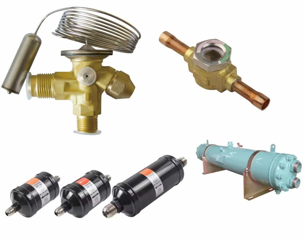
Une installation correcte du TXV nécessite la bonne vanne et le bon orifice, contact d'ampoule fiable et retour de pression précis. Une mauvaise installation peut ralentir le refroidissement, surchauffe instable ou retour de liquide. Les ajustements répétés des valves résolvent rarement ces problèmes sous-jacents.
Ce guide couvre les nouvelles installations et les remplacements de TXV dans les chambres froides à détente directe.. Suivre les manuels spécifiques des équipements et des vannes pour la tuyauterie, méthodes de connexion et limites d'acceptation.
Sécurité: Seuls des techniciens en réfrigération qualifiés doivent effectuer ce travail. Verrouiller l’alimentation électrique, récupérer le réfrigérant si nécessaire et confirmer les conditions de pression sûres avant d'ouvrir le système. Pour les réfrigérants inflammables, suivre la ventilation spécifique au système, procédures de détection des fuites et de contrôle de l’allumage.
Comprendre la disposition de l'installation du TXV
Dans un évaporateur multicircuit typique, le réfrigérant passe par le TXV et le distributeur avant d'entrer dans les circuits de l'évaporateur. L'ampoule de détection surveille le tuyau d'aspiration de sortie. L'égaliseur externe fournit un retour de pression depuis la région de sortie correspondante..

Chiffre 1. Disposition conceptuelle pour un évaporateur avec égalisation externe. Suivez le dessin de l'équipement pour connaître le routage et les connexions réels..
| Composant | Fonction | Vérification de l'installation |
|---|---|---|
| TXV | Compte le réfrigérant dans l’évaporateur | Confirmer le modèle, sens d'écoulement et accès aux services |
| Distributeur | Divise le réfrigérant entre les circuits | Vérifier la buse, nombre de circuits et orientation |
| Ampoule de détection | Suit la température du tuyau de sortie | Vérifier l'emplacement, contact, sangles et isolation |
| Égaliseur externe | Transmet la pression d'aspiration à la valve | Confirmez la source de pression et une connexion claire |
| Points de test | Prise en charge des contrôles de température et de pression | Faites correspondre les emplacements de mesure et autorisez des tests répétés |
Avis: L'ampoule de détection ne fonctionne pas’mesurer la température ambiante. Son tube capillaire et l'égaliseur externe remplissent différentes fonctions; ne les échangez jamais.
Clapet anti-retour et composants correspondants
Tailles de connexion correspondantes’ne garantit pas la compatibilité. Certains TXV utilisent des orifices interchangeables, un corps de vanne peut donc servir plusieurs capacités.

| Article | Confirmer | Éviter |
|---|---|---|
| Réfrigérant | Compatibilité exacte des réfrigérants | En supposant que des réfrigérants similaires utilisent la même vanne |
| Application | Plage d'évaporation et service de refroidissement/congélateur | Remplacer une configuration moyenne température sans vérifier |
| Vanne et orifice | Modèle complet et code d'orifice | Vérification uniquement du corps de vanne |
| Égalisation | Retour de pression interne ou externe | Omettre une connexion d'égaliseur externe |
| Capacité | Charger, conditions du liquide d'entrée et chute de pression disponible | Sélection uniquement par puissance du compresseur |
| Charge d'élément | Gamme d'applications et toute fonctionnalité MOP | Ignorer les suffixes du modèle |
| Relations | Taille, type de joint et pression nominale | Traiter une forme physique comme une approbation |
| Distributeur | Corps, disposition des buses et des circuits | En supposant que l'ancien distributeur convient à chaque vanne de remplacement |
Pour une demande de remplacement, fournir l'ancienne plaque signalétique de la vanne, identification des orifices, réfrigérant, modèle d'évaporateur et conditions de conception. Une photo de valve à elle seule peut ne pas identifier le remplacement correct.
Avis: Toujours à choisir un fournisseur? Explorez notre Aperçu du fabricant du TXV, puis confirmer la compatibilité des réfrigérants, disponibilité des orifices et support technique pour votre application.
Interne vs. Péréquation externe
| Type de vanne | Source de pression | Considération principale |
|---|---|---|
| TXV égalisé en interne | Sortie de vanne par un passage interne | Maintenir la chute de pression de l’évaporateur dans les limites du fabricant |
| TXV égalisé en externe | Près de la sortie de l'évaporateur via une conduite séparée | Tenir compte de la chute de pression de l'évaporateur et du distributeur |
Un distributeur et ses tubes ajoutent une perte de charge. Pour la disposition conventionnelle TXV/distributeur dans ce guide, utiliser une égalisation externe comme l'exige le fabricant de l'équipement. Ne bouchez jamais un port d'égalisation externe et n'actionnez jamais la vanne..
Installer le corps de vanne et les connexions

Confirmer la direction du flux et l'accès
Suivez la flèche de la valve et les instructions du modèle. Enfiler’t déduire la direction du flux à partir de la forme du corps ou supposer que chaque TXV prend en charge le flux inverse.
Laissez de la place pour atteindre le capuchon de réglage et les pièces réparables. Pour les modèles à orifices interchangeables, laisser suffisamment d’espace pour un remplacement futur.
Prévenir le stress mécanique
Soutenez la tuyauterie afin que la vanne ne’ne supporte pas le poids du tuyau ou la contrainte d'alignement. Évitez de forcer les connexions en position.
Acheminer le capillaire du bulbe sans coudes prononcés, tension ou contact avec des bords abrasifs. Ne tirez jamais sur le capillaire pour repositionner l’ampoule.
Utilisez la bonne méthode de connexion
| Connexion | Contrôles clés |
|---|---|
| Éclater | Qualité du torchage, nettoyer les faces d'étanchéité, alignement et couple spécifié |
| Brasé | Matériaux compatibles, contrôle de la chaleur et propreté intérieure |
| Raccord réparable | Joints corrects, séquence d'assemblage et méthode de serrage |
Utiliser une purge à l'azote sec selon la procédure de brasage approuvée. Gardez les contaminants hors du circuit réfrigérant. Ne jamais tester la pression avec de l'oxygène.
Suivre le manuel de la vanne pour le démontage, protection thermique et préparation des joints. Différentes conceptions de vannes peuvent nécessiter différentes méthodes; enfiler’N'appliquez pas une procédure d'emballage humide ou de chauffage à chaque modèle.
Montez correctement l’ampoule de détection
L'ampoule a besoin d'un contact thermique ferme avec le tuyau d'aspiration. L'isolation ne peut pas compenser une ampoule desserrée ou un entrefer.
Choisissez une section de tuyau de sortie appropriée
Préférez une ligne droite adaptée, section d'aspiration horizontale à proximité de la sortie de l'évaporateur. Alignez l'ampoule avec le tuyau et évitez les endroits qui collectent du liquide ou de l'huile..
Gardez l'ampoule à l'écart des sources de chaleur externes et des gros composants qui peuvent fausser sa réponse en température.. Enfiler’Ne le déplacez pas en aval d'un échangeur de chaleur à aspiration qui ajoute de la chaleur au-delà de la sortie de l'évaporateur..
Suivre les positions d'horloge spécifiques au modèle
Vérifiez le diamètre extérieur du tuyau et les instructions de la vanne avant de choisir une position d'horloge..
Par exemple, certaines instructions Danfoss T2/TE2 spécifient des régions de montage 1 pour 4 heures ou 8 pour 11 heures. Appliquer ces instructions uniquement aux produits et aux conditions qu'elles couvrent.

Installation de l'ampoule de détection TXV
Enfiler’t transformer une seule position d'horloge ou un seuil de diamètre de tuyau en une règle universelle. Évitez le bas du tuyau d'aspiration, où l'huile et le liquide peuvent affecter la lecture.
Vérifiez séparément les applications de tuyaux verticaux
Les positions d'horloge à tube horizontal ne’t définir les exigences de montage vertical. Vérifiez si le fabricant autorise le sens et la disposition réels du flux..
Certains guidages Sporlan permettent une section d'aspiration verticale descendante dans des conditions spécifiées. Cela ne’Je n'approuve pas chaque contremarche, piège ou emplacement vertical.

Inspecter Contacter, Montage et isolation

Chiffre 2. Vérifiez le contact de l'ampoule avant d'ajouter de l'isolant. Cette vue latérale ne’t spécifier une position d'horloge de montage.
| Vérifier | Pratique correcte | Action corrective |
|---|---|---|
| Surface de contact | Tuyau propre et contact d'ampoule plein | Éliminer la contamination et éliminer les lacunes |
| Montage | Sangles ou pinces spécifiées par le fabricant | Sécurisez toute ampoule qui glisse ou tourne |
| Isolation | Respecter les exigences en matière de couverture et de protection contre l'humidité | Réparer les lacunes, sections lâches ou isolation humide |
| Alentours | Minimiser l’influence thermique externe | Examinez les radiateurs à proximité, tuyaux chauds et gros raccords |
| Capillaire | Maintenir une douceur, itinéraire pris en charge | Tension correcte, risques de plis et d’abrasion |
Dans les systèmes multi-évaporateurs, chaque ampoule doit suivre sa propre sortie d'évaporateur. Enfiler’t déplacer les ampoules vers un collecteur d'aspiration commun sans approbation de conception.
Connectez l'égaliseur externe
L'égaliseur doit fournir une pression qui représente la conduite d'aspiration à l'emplacement de l'ampoule..
Une disposition courante place la connexion à proximité et immédiatement en aval de l'ampoule.. Certaines conceptions d'équipement utilisent à la place un collecteur approprié ou une connexion de retour..
| État du site | Que vérifier |
|---|---|
| Régulateur de pression de l'évaporateur près de la sortie | Prendre la pression du côté de l'évaporateur comme la conception l'exige |
| Plusieurs évaporateurs partagent un collecteur d'aspiration | Confirmer la référence de pression pour chaque circuit |
| Le robinet de l'égaliseur se trouve loin de l'ampoule | Évaluer la perte de pression entre les deux emplacements |
| La ligne d'égalisation est pliée ou bloquée | Restaurer le chemin de pression avant de régler la vanne |
| Le port externe n'a pas de connexion | Complétez la connexion requise; ne jamais fonctionner avec un port plafonné |
Avis: Vérifier la relation de pression, pas seulement si le robinet se trouve avant ou après l'ampoule. Une vanne de régulation de pression ou une perte de conduite importante entre les emplacements peut invalider le retour d'information..
Installer et vérifier le distributeur de réfrigérant
Le distributeur répartit le mélange réfrigérant entre des circuits d'évaporation parallèles. Sa buse, les tubes et la charge de fonctionnement influencent tous la distribution.
Pour des informations sur le fonctionnement et les conceptions, lisez notre guide pour fonction et types du distributeur de réfrigérant.

Le distributeur doit-il toujours pointer vers le bas?
Non. Suivre les instructions spécifiques au distributeur et à l'évaporateur.
Certains distributeurs Sporlan permettent plusieurs orientations. L'alimentation verticale vers le haut ou vers le bas peut améliorer les performances dans diverses conditions, en fonction de la conception et de la connexion TXV.
Enfiler’t modifier un agencement de tuyauterie approuvé simplement pour forcer une orientation vers le bas.
Vérifiez la buse et les tubes de distribution
| Article | Inspection |
|---|---|
| Ajutage | Confirmer l'identification, taille et montage correct |
| Connexion TXV au distributeur | Conserver la disposition spécifiée; éviter les extensions ou les coudes non approuvés |
| Tubes de distribution | Vérifier le nombre de circuits, diamètre, longueur et acheminement |
| Chemins de flux | Recherchez des tubes écrasés, blocage de soudure ou prises bouchées |
La longueur du tube affecte la capacité et la chute de pression. Enfiler’Je ne raccourcis pas une branche simplement pour simplifier le routage, ou confondre l'orifice TXV avec le gicleur distributeur.
Si les circuits présentent des modèles de gel différents, enquêter sur le flux d'air, charge et distribution avant d'augmenter le débit TXV.
Effectuer les vérifications préalables au démarrage
Enfiler’Ne démarrez pas le système immédiatement après avoir connecté la vanne..
| Vérifier | Confirmer avant le démarrage |
|---|---|
| Test de fuite | Effectuez le test spécifié et enregistrez le résultat |
| Évacuation et déshydratation | Répondre aux exigences de l'équipement et vérifier les performances de maintien du vide |
| Réfrigérant | Confirmer le réfrigérant, procédure de facturation et relevé de facturation |
| Tuyauterie et vannes | Vérifier les positions de fonctionnement, bouchons et supports d'étanchéité |
| Système électrique | Vérifier l'approvisionnement, câblage, protection et mise à la terre |
| Évaporateur | Vérifiez les ventilateurs, dégagement et drainage du flux d'air |
| Contrôles | Vérifier la température, dégivrer, paramètres de retard du ventilateur et d'alarme |
| Instruments | Confirmer les points de test, sélection de réfrigérant et unités de pression |
Enfiler’t copier la pression d'essai, limites d'évacuation ou quantités de charge d'une autre chambre froide. Utilisez les exigences de ce système.
Vérifier le fonctionnement initial et la récupération après dégivrage
Une température ambiante en baisse confirme une activité de refroidissement, mais ce n'est pas le cas’t prouver le contrôle correct du TXV dans toutes les conditions de fonctionnement.
Évaluer chaque étape de fonctionnement
| Scène | Observer | Éviter |
|---|---|---|
| Démarrage et déroulement | Tendances de pression, refroidissement, fonctionnement des ventilateurs et du compresseur | Définition de la surchauffe finale à partir d'un instantané de démarrage |
| Charge constante représentative | Surchauffe de sortie, approvisionnement en liquide et stabilité | Vérifier seul la température ambiante |
| Près du point de consigne | Contrôle et cyclage à faible charge | Traiter un test en salle vide comme une validation à pleine charge |
| Récupération de dégivrage | Temps d'égouttement, redémarrage du ventilateur, indicateurs d'alimentation en liquide et de retour d'eau | Confondre un retard de contrôle avec un défaut de composant |
Après dégivrage électrique, le contrôleur peut maintenir les ventilateurs éteints pendant le temps d'égouttement ou le refroidissement du serpentin. Vérifiez la séquence de contrôle avant de diagnostiquer un défaut de ventilateur ou de TXV.
Faites correspondre les intervalles de dégivrage, conditions de terminaison et temps d'égouttement vers l'équipement et l'application. Évitez les paramètres universels.
Faire correspondre les mesures de température et de pression
Enregistrer la température du tuyau et la pression correspondante à proximité de la sortie de l'évaporateur. Identifier le réfrigérant, unités de pression et emplacements de test exacts.
Enfiler’t combiner la pression d'entrée du compresseur avec une température de sortie de l'évaporateur à distance sans évaluer la perte de pression dans la conduite d'aspiration.
Pour les calculs et les procédures de réglage, voir notre Guide de réglage et de dépannage de la surchauffe TXV.
Ajustez uniquement lorsque les résultats le justifient
Un nouveau TXV peut fonctionner correctement sans ajustement sur le terrain. Confirmez d’abord la compatibilité de la vanne, installation, débit d'air et alimentation en liquide.
Si l'équipement nécessite un changement de réglage, suivre la procédure spécifique à la vanne, enregistrer le réglage et permettre au système de se stabiliser. N'utilisez jamais de réglage pour masquer un défaut de tuyauterie ou d'alimentation..
Résoudre les problèmes après l'installation
Utiliser les symptômes pour guider l’inspection, ne pas identifier seul un composant défaillant.
| Symptôme | Premiers contrôles | Éviter |
|---|---|---|
| Mauvais refroidissement et surchauffe élevée | Mesures, approvisionnement en liquide, restrictions, valve et orifice | Augmentation immédiate du débit TXV |
| Faible surchauffe | Flux d'air, charger, contact gel et ampoule | Diagnostiquer le retour de crue dû au seul gel des canalisations |
| Pression et surchauffe fluctuantes | Charger les modifications, réponse de l'ampoule, dimensionnement des vannes et stabilité de l'alimentation | Ajustements répétés en va-et-vient |
| Faible pression d'aspiration après remplacement | Spécification de remplacement et tout le chemin du liquide | Remplacer à nouveau le TXV sans diagnostic |
| Problèmes seulement après le dégivrage | Retard du ventilateur, récupération des aliments, chauffage et commandes à ampoule | Réglage de la surchauffe pendant le transitoire |
| Performances inégales des circuits | Répartition du flux d'air, tubes distributeurs et dérivation | En supposant que le TXV provoque chaque déséquilibre |
Si le compresseur cogne, un retour de crue sévère semble probable, ou les dispositifs de protection se déclenchent à plusieurs reprises, suivre la procédure d'arrêt de l'équipement et enquêter. Enfiler’Ne pas poursuivre les ajustements d'essai.
Enregistrer les résultats de l’installation et de la mise en service
Utilisez les enregistrements suivants pour le transfert. Saisir les critères d'acceptation à partir des documents d'équipement; les formulaires ne’t définir des limites universelles.
Dossier d'équipement et d'installation
| Article | Enregistrer |
|---|---|
| Projet, date et technicien | ______ |
| Modèles d'unités de condensation et d'évaporateurs | ______ |
| Enregistrement du réfrigérant et de la charge | ______ |
| Modèle TXV et code orifice | ______ |
| Distributeur, nombre de buses et de circuits | ______ |
| Emplacement de l'ampoule, diamètre du tuyau et référence photo | ______ |
| Emplacement de l'égaliseur et référence de la photo | ______ |
| Résultats des tests d'étanchéité et d'évacuation | ______ |
| Manuel d'installation et révision | ______ |
Mesures de fonctionnement
Remplir une fiche distincte pour chaque évaporateur ou circuit indépendant.
| Article | Déroulant | Charge constante | Récupération après dégivrage |
|---|---|---|---|
| Temps, température ambiante et ambiante | ______ | ______ | ______ |
| Chargement des produits et activité de la porte | ______ | ______ | ______ |
| Pression et unités de sortie de l'évaporateur | ______ | ______ | ______ |
| Température du tuyau à l'emplacement correspondant | ______ | ______ | ______ |
| Température de saturation correspondante | ______ | ______ | ______ |
| Surchauffe sortie évaporateur | ______ | ______ | ______ |
| Emplacement des tests d'alimentation en liquide et de sous-refroidissement | ______ | ______ | ______ |
| Ventilateur, état de dégivrage et d'alarme | ______ | ______ | ______ |
| Modifications et lectures de suivi | ______ | ______ | ______ |
Statut de transfert
- Critères d'acceptation et référence du document: ______.
- Conditions de fonctionnement vérifiées par le technicien: ______.
- Conditions qui nécessitent encore des tests: ______.
- Travail remarquable et date de suivi: ______.
- Approbation du technicien et du client: ______.
Si le site ne peut pas prendre en charge un test à pleine charge, enregistrer "Vérification du chargement complet en attente." Enfiler’ne pas prétendre à une validation complète à partir d'un test partiel.
FAQ d'installation du TXV
Q1.L'ampoule doit-elle reposer 1.5 Compteurs du compresseur?
Aucune distance universelle ne s’applique.
Choisissez un emplacement qui représente la sortie de l'évaporateur et suivez les instructions de l'équipement et des vannes..
Q2.Le capillaire de l'ampoule peut-il remplacer l'égaliseur externe?
Non. Le capillaire transmet la pression à l'intérieur de l'élément de détection.
L'égaliseur transmet la pression du système à la vanne. Gardez leurs fonctions et connexions séparées.
Q3.Pouvez-vous remettre le système après un test de fuite réussi?
Pas encore.
Vérifier les performances opérationnelles et les contrôles pertinents, puis enregistrez les résultats et les éventuelles limites du test.
Q4.Que devez-vous envoyer pour une assistance technique à distance?
Fournir les plaques signalétiques des vannes et des évaporateurs, détails du réfrigérant, photos de la tuyauterie globale, gros plans sur l'ampoule et l'égaliseur, et mesures avec emplacements de test.
Si le problème survient uniquement lors du pull-down, faible charge ou récupération de dégivrage, inclure ce timing et l'état du contrôleur. Une photo d'un manomètre fournit rarement à elle seule suffisamment d'informations.
Conclusion
Faites correspondre les composants, installer un retour précis de température et de pression, et vérifier le fonctionnement dans les conditions pertinentes. Conservez des enregistrements clairs afin que les installateurs et les équipes de service puissent distinguer les défauts d'installation de la charge., problèmes d'approvisionnement et de contrôle.