Using one condensing unit for multiple cold rooms means one outdoor condenserende eenheid supplies refrigerant to two or more evaporators, meestal één verdamper voor elke kamer, via een gedeelde vloeistofleiding en een gedeelde zuigretour.
Deze opstelling kan de apparatuurkosten verlagen, buitenruimte besparen, en het onderhoud vereenvoudigen. Echter, het werkt alleen goed als de kamertemperatuur is, belastingsomstandigheden, ontwerp van leidingen, en besturingslogica komen allemaal overeen met de toepassing.
Het kernidee is eenvoudig: each koude kamer must cool independently.
Eén kamer zou om koeling moeten vragen, bereik ingestelde temperatuur, en stop met koelen zonder de andere kamers te dwingen te overkoelen of de controle te verliezen.
Wanneer dit ontwerp zinvol is
A one-condensing-unit multi-room design works best when the koude kamers have similar temperatures and similar operating conditions.
Goede toepassingen:
| Projecttype | Geschiktheid | Waarom |
|---|---|---|
| Twee of meer koelruimtes | Goed | Soortgelijke kamertemperaturen maken de regeling eenvoudiger |
| Twee of meer vriesruimtes | Meestal goed | Dezelfde zuigconditie werkt beter |
| Meerdere kleine koelcellen in één faciliteit | Goed | Bespaart ruimte en vermindert de hoeveelheid apparatuur |
| Projecten met een beperkt installatieoppervlak buiten | Goed | Eén condensatieunit heeft minder ruimte nodig |
Toepassingen die extra zorg nodig hebben:
Als alle kamers qua temperatuur dichtbij blijven, één gedeelde zuigconditie kan vaak het hele systeem ondersteunen. Als de ene kamer als vriezer fungeert en de andere als koelmachine, het ontwerp heeft extra drukcontrole nodig.
Hoe het systeem werkt
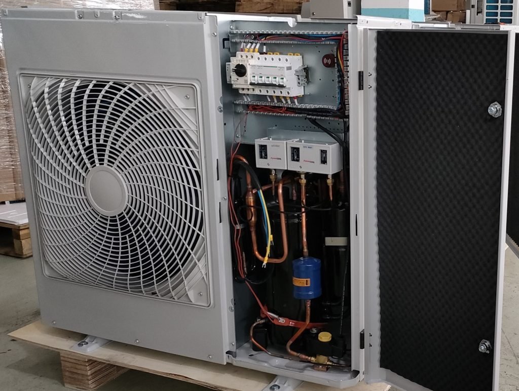
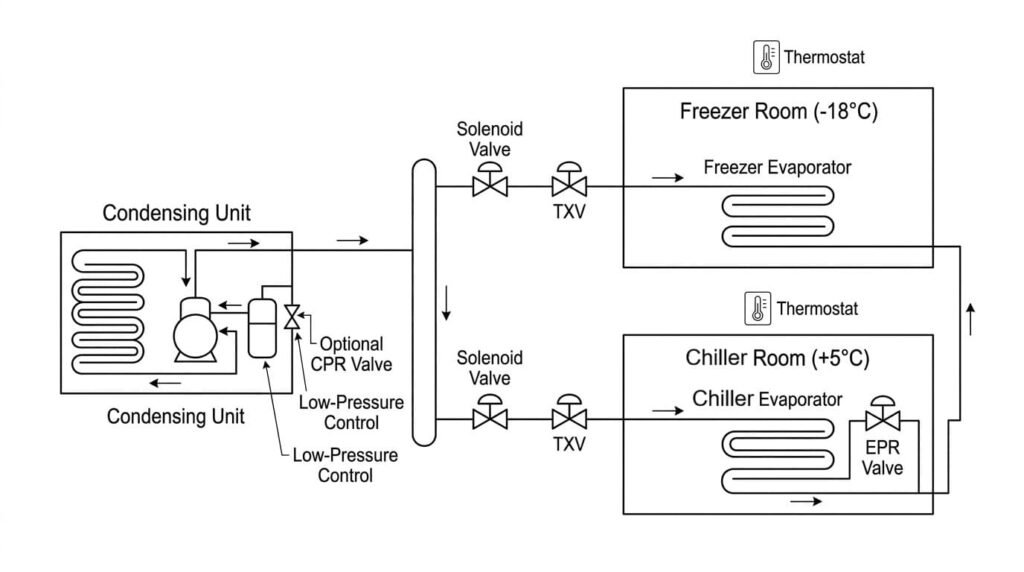
In dit ontwerp, de condenserende eenheid acts as the refrigeration source, en elke koude kamer fungeert als een onafhankelijke koelzone.
Elke kamer heeft doorgaans zijn eigen regel- en koelmiddeltoevoercomponenten.
Basiscomponentindeling:
De thermostaat in elke kamer regelt de magneetklep van die kamer.
Wanneer de kamertemperatuur boven het instelpunt stijgt, de thermostaat opent de magneetklep. Het koelmiddel stroomt vervolgens naar de verdamper van die kamer. Wanneer de kamer het instelpunt bereikt, de thermostaat sluit de magneetklep en stopt de koelmiddelstroom naar die kamer.
Deze opstelling geeft elke kamer een onafhankelijke aan/uit-regeling voor koeling, terwijl alle kamers één condensatie-unit delen.
Koelcircuit voor meerdere koelruimtes
Kamers met dezelfde temperatuur: De eenvoudigste configuratie
Kamers met dezelfde temperatuur creëren de eenvoudigste en meest betrouwbare één-op-veel-opstelling.
Bijvoorbeeld, if you have three koude kamers at +2°C, +3° C, en +4°C, Eén gedeelde condensorunit werkt vaak goed omdat het systeem voor alle drie de kamers een vergelijkbare zuigconditie kan gebruiken.
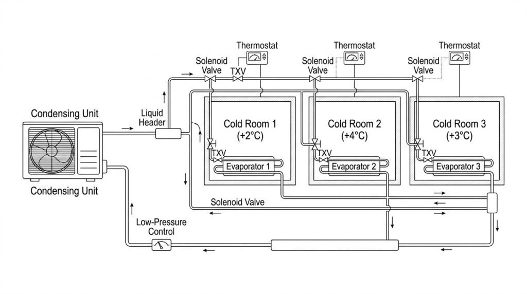
Systeemindeling met dezelfde temperatuur:
Waarom deze lay-out goed werkt:
Bij dit soort projecten, het systeem regelt meestal goed zolang de belastingberekeningen worden uitgevoerd, leidingen, en componentselectie correct zijn.
Kamers met gemengde temperaturen: Chiller en vriezer in één unit
When one condenserende eenheid serves a chiller and a freezer, het ontwerp wordt moeilijker.
De reden is: de vriezer heeft een lagere zuigdruk nodig.
Als de koelmachine dezelfde lage zuigkracht direct deelt, de verdamper van de koelmachine kan te koud worden. Dat kan overkoeling veroorzaken, spoel glazuur, onstabiele kamertemperatuur, of zelfs productbevriezing in de koelmachine.
Voorbeeld:
In deze situatie, een eenvoudig gedeeld systeem presteert op zichzelf meestal niet goed.
De koelruimtebranche heeft vaak behoefte aan een EPR-klep.
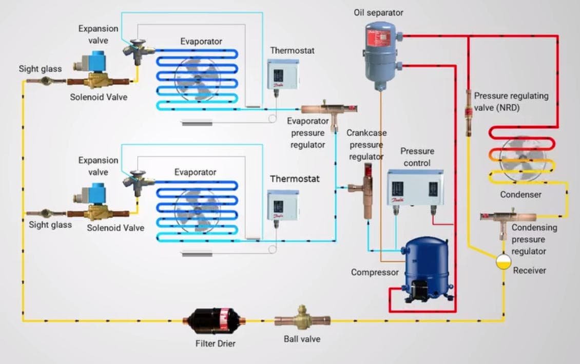
Wat een EPR-klep doet
Een EPR-klep zorgt ervoor dat de warmere kamer een hogere verdamperdruk behoudt.
Meestal installeer je de EPR-klep in de aanzuigleiding van de warmere kamer, na de verdamper en vóór de gemeenschappelijke zuigcollector.
EPR-kleplogica:
Met deze regeling:
-
De vriestak volgt de lagere zuigkracht die hij nodig heeft.
-
De koelertak blijft op een hogere verdamperdruk omdat de EPR-klep deze daar vasthoudt.
Zo kan één condensatieunit twee ruimtes met verschillende temperatuur veiliger bedienen.
Wanneer moet een EPR-klep worden gebruikt?
- Als het verschil in kamertemperatuur binnen 5°C blijft, één condensatieunit werkt meestal goed voor beide kamers. De bediening blijft eenvoudiger en het systeem draait stabieler. Geen EPR-klep nodig.
- Als het temperatuurverschil groter is dan 8°C ~ 10°C, kan het niet behandelen als een eenvoudige opstelling met gedeelde eenheden. Meestal moet u het systeem evalueren en een EPR-klep toevoegen, zeker voor een koel-plus-vriescombinatie.
Bijvoorbeeld: een koelruimte van +5°C en een vriesruimte van -18°C hebben een groot temperatuurverschil, Normaal gesproken moet u dus een EPR-klep toevoegen. Anders, de koelertak kan te koud worden.
Wanneer een reanimatieklep kan helpen
Sommige projecten hebben ook een CPR-klep in de buurt van de compressoraanzuiging.
Een CPR-klep beschermt de compressor tijdens het opstarten of hete pull-down. Als meerdere ruimtes tegelijkertijd om koeling vragen, of als warm product de kamers binnenkomt, de zuigdruk kan snel stijgen. Die hoge zuigdruk kan de compressor overbelasten.
CPR-kleplogica:
| Vraag | Antwoord |
|---|---|
| Waarom een CPR-ventiel gebruiken?? | Bescherm de compressor tijdens zware belasting |
| Waar installeer je het? | In de buurt van de compressoraanzuiging |
| Wanneer is het nuttig? | Hete pull-down, zware opstartbelasting, veelvuldig openen van de deur |
| Heeft elk project dit nodig?? | Nee, maar sommige projecten met gemengde of zware belasting doen dat wel |
Hoe de koelcapaciteit wordt verdeeld
Dit is een van de meest gestelde vragen van klanten:
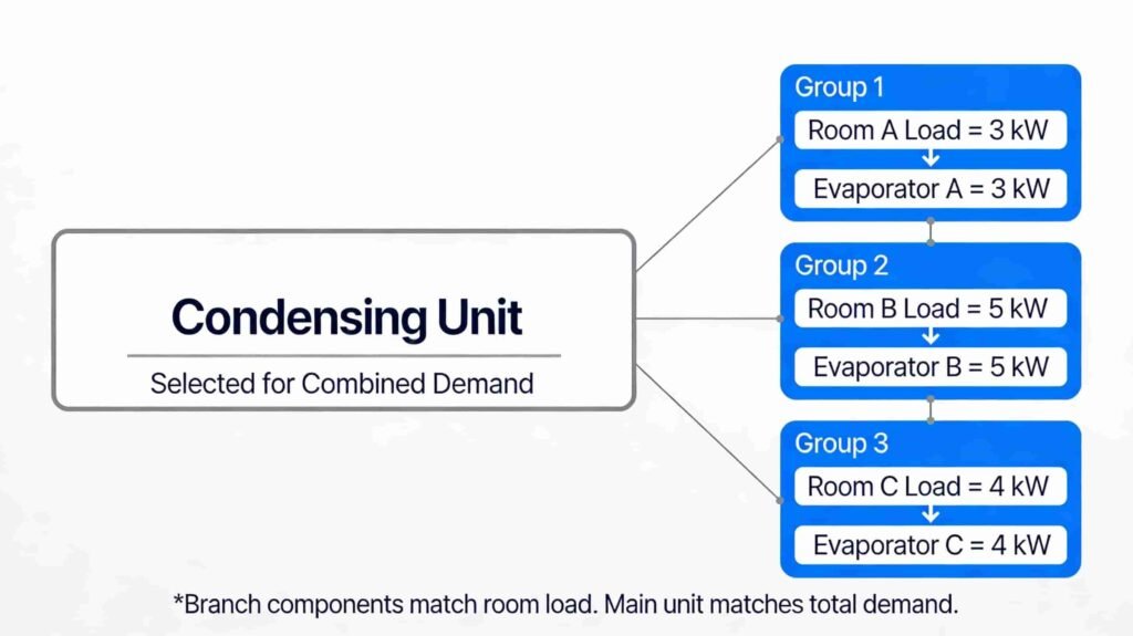
If one condenserende eenheid serves several rooms, hoe verdeelt het systeem de koelcapaciteit?
Het korte antwoord is: het systeem verdeelt koeling niet door giswerk. Een juiste componentselectie bepaalt hoe het systeem de koeling verdeelt.
Koeldistributie voor koude ruimtes
Logica van capaciteitsverdeling:
Bijvoorbeeld:
Uitsplitsing van de monsterlading:
Selectie resultaat:
Elke verdamper verwerkt de belasting van zijn eigen kamer. De condensorunit dekt de totale vraag wanneer meerdere ruimtes tegelijkertijd om koeling vragen.
Dat betekent:
-
Jij hoeft niet wijs handmatig “30% koeling” toe aan de ene kamer en “70%” aan een andere kamer.
-
Je maat elke tak op de juiste maat.
-
U berekent de hoofdeenheid op maat voor de gecombineerde vraag.
Eenvoudige regeltabel
Deze tabel helpt klanten te begrijpen wanneer een eenvoudig één-op-veel-systeem werkt en wanneer er extra controles nodig zijn.
Wanneer moet u een eenvoudig systeem gebruiken en wanneer moet u drukregeling toevoegen?:
Hoe u het systeem stap voor stap configureert
Een goed ontwerp met meerdere kamers met één condensatieunit volgt meestal dit proces:
Stap 1: Bevestig basisprojectgegevens
Stap 2: Bereken de belasting voor elke kamer
U dient elke kamer afzonderlijk te berekenen.
Hoofdladingsitems:
Deze stap geeft u de benodigde verdampercapaciteit voor elke kamer.
Stap 3: Selecteer één verdamper voor elke kamer
Maak niet alle verdampers hetzelfde, tenzij de kamers echt dezelfde belasting en dezelfde bedrijfsomstandigheden hebben.
Stap 4: Selecteer de condensatie-eenheid voor gecombineerde vraag
In deze stap gaan veel projecten fout.
Some people size the condenserende eenheid only by looking at one room. Die aanpak zorgt vaak voor problemen tijdens het opstarten, zwaar gebruik, of gelijktijdige koelvraag.
Selectiechecklist condensatie-eenheid:
De condensatie-unit moet onder reële bedrijfsomstandigheden voldoen aan de systeemvraag, niet alleen ideale laboratoriumomstandigheden.
Stap 5: Ontwerp de koelmiddelleidingen
Een systeem met meerdere verdampers heeft een goed leidingontwerp nodig, omdat het zowel bij vollast als bij deellast moet werken.
Regels voor leidingen:
Tegenwoordig kan een systeem werken waarbij alle kamers samen afkoelen, dan kan er vanavond slechts één kleine kamer om koeling vragen. Uw leidingwerk moet aan beide voorwaarden voldoen.
Stap 6: Voeg kamer-voor-kamer bedieningselementen toe
Onafhankelijke ruimtebediening is het hart van een meerkamersysteem.
Standaard besturingsregeling:
Elke kamer moet zijn eigen koelmiddeltoevoer regelen. Zonder dat, één kamer kan blijven koelen als deze niet langer gekoeld hoeft te worden.
Stap 7: Gebruik de afpompregeling
Pump-down-regeling helpt de compressor te beschermen.
Pompvolgorde:
Deze methode helpt de migratie van vloeibaar koelmiddel tijdens uit-cycli te verminderen.
Stap 8: Plan het ontdooien voor elke kamer
Verschillende kamers bouwen vaak vorst op in verschillende snelheden.
Ontdooifactoren:
Het is doorgaans beter om de ontdooischema’s te spreiden in plaats van alle verdampers tegelijkertijd te ontdooien.
Voorbeeld 1: Drie vergelijkbare koelruimtes
Dit voorbeeld toont een standaardproject met dezelfde temperatuur.
Projectgegevens:
Omdat de kamertemperatuur dichtbij is, één gedeelde condensatie-eenheid is meestal zinvol.
Aanbevolen configuratie:
Bedieningslogica:
Dit type project biedt de beste balans tussen eenvoud, kosten, en stabiele werking.
Voorbeeld 2: Eén koelmachine en één vriezer
Dit voorbeeld toont een project met gemengde temperaturen.
Projectgegevens:
Aanbevolen configuratie:
Bedieningslogica:
Dit ontwerp kan goed werken, maar het heeft een betere drukcontrole en een zorgvuldiger opstelling nodig dan een systeem met dezelfde temperatuur.
Voorbeeld 3: Vergelijking van energieverbruik
Vraag: “Hoeveel elektriciteit kan 1 condensatie-eenheid bespaart wanneer deze dient 3 koude kamers, vergeleken met het gebruik 3 afzonderlijke condensatie-units?”
Goed, er is geen vast nummer.
Voor een project als het bovenstaande voorbeeld: één condensatie-eenheid dient 3 koude kamers usually bespaart ongeveer 5% naar 15% elektriciteit (als u een inverter-condensatie-eenheid gebruikt, kunt u ongeveer besparen 25% naar 35%) vergeleken met 3 afzonderlijke condensatie-units wanneer de kamers vergelijkbare temperaturen hebben, vergelijkbare openingstijden, en een goed leidingontwerp.
Eenvoudig antwoord:
Waarom één apparaat energie kan besparen:
-
Eén grotere condensatie-unit werkt vaak efficiënter dan drie kleine units.
-
Een gedeeld systeem kan fietsverliezen verminderen.
-
Eén systeem kan de capaciteit soepeler gebruiken als de ruimtebelasting verandert.
Maar spaargeld kan verdwijnen:
Makkelijk voorbeeld:
Als 3 afzonderlijke eenheden gebruiken 100 kWh/dag, één gedeelde eenheid voor hetzelfde 3 soortgelijke kamers kunnen ongeveer gebruiken 85 naar 92 kWh/dag.
KENNISGEVING: De werkelijke besparing is afhankelijk van de kamertemperatuur, diversiteit laden, leidingen, en besturingsontwerp.
Veelvoorkomende fouten
Meest voorkomende ontwerpfouten:
Conclusie
Eén condensatieunit kan meerdere koelruimtes goed aansturen als de kamertemperatuur op elkaar is afgestemd, maat elke verdamper correct, en ontwerp de bedieningselementen en leidingen met zorg.
Voor projecten met gemengde temperaturen, voeg de juiste drukregelaars toe, zoals EPR, om de stabiliteit van de ruimte en de productkwaliteit te beschermen. Een goed gepland één-op-veel-systeem kan de kosten verlagen, Bespaar ruimte, en betrouwbare prestaties leveren.