Using one condensing unit for multiple cold rooms means one outdoor 응축 장치 supplies refrigerant to two or more evaporators, 일반적으로 각 방마다 하나의 증발기, 공유 액체 라인과 공유 흡입 복귀를 통해.
이 설정으로 장비 비용을 낮출 수 있습니다., 야외 공간을 절약하다, 유지 관리를 단순화하고. 하지만, 실내 온도가 좋을 때만 잘 작동합니다., 부하 조건, 배관 디자인, 및 제어 로직은 모두 애플리케이션과 일치합니다..
핵심 아이디어는 간단하다: each 추운 방 must cool independently.
한 방에는 냉방이 필요합니다, 설정된 온도에 도달, 다른 방을 과냉각시키거나 통제력을 잃지 않고 냉방을 중단하세요..
이 디자인이 의미가 있을 때
A one-condensing-unit multi-room design works best when the 차가운 방 have similar temperatures and similar operating conditions.
좋은 응용 프로그램:
| 프로젝트 유형 | 적당 | 왜 |
|---|---|---|
| 2개 이상의 냉각실 | 좋은 | 유사한 실내 온도로 인해 제어가 더 쉬워집니다. |
| 2개 이상의 냉동실 | 보통 좋음 | 동일한 흡입 조건이 더 잘 작동함 |
| 한 시설에 여러 개의 작은 냉장실 | 좋은 | 공간 절약 및 장비 수량 감소 |
| 옥외 설치 면적이 제한된 프로젝트 | 좋은 | 하나의 응축 장치는 더 적은 공간을 필요로 합니다. |
특별한 관리가 필요한 애플리케이션:
모든 방의 온도가 비슷하게 유지된다면, 하나의 공유 흡입 조건이 전체 시스템을 지원할 수 있는 경우가 많습니다.. 한 방은 냉동고로 작동하고 다른 방은 냉각기로 작동하는 경우, 디자인에 추가적인 압력 제어가 필요함.
시스템 작동 방식
이 디자인에서는, 그만큼 응축 장치 acts as the refrigeration source, 각 냉장실은 독립적인 냉각 구역으로 작동합니다..
각 방에는 일반적으로 자체 제어 및 냉매 공급 구성 요소가 포함됩니다..
기본 구성 요소 레이아웃:
각 방의 온도 조절 장치는 해당 방의 솔레노이드 밸브를 제어합니다..
실내 온도가 설정치 이상으로 올라가면, 온도 조절 장치가 솔레노이드 밸브를 엽니다.. 그러면 냉매는 해당 방의 증발기로 흐릅니다.. 방이 설정값에 도달하면, 온도 조절 장치는 솔레노이드 밸브를 닫고 해당 방으로의 냉매 흐름을 중단합니다..
이 설정은 모든 방이 하나의 응축 장치를 공유하는 동안 각 방에 독립적인 온/오프 냉각 제어를 제공합니다..
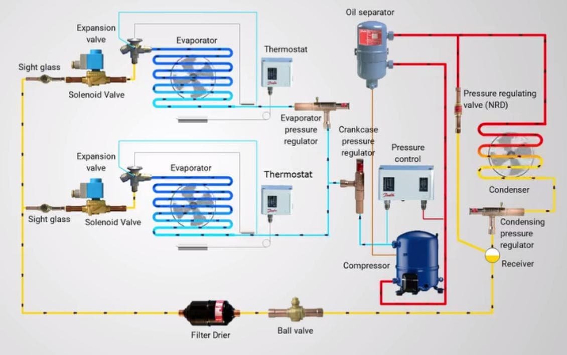
다중 냉장실 냉동 회로
같은 온도의 방: 가장 간단한 구성
동일한 온도의 방은 가장 간단하고 안정적인 일대다 설정을 만듭니다..
예를 들어, if you have three 차가운 방 at +2°C, +3°C, +4°C, 하나의 공유 응축 장치는 시스템이 세 방 모두에 대해 유사한 흡입 조건을 사용할 수 있기 때문에 종종 잘 작동합니다..

동일 온도 시스템 레이아웃:
이 레이아웃이 효과적인 이유:
이런 유형의 프로젝트에서는, 시스템은 일반적으로 부하 계산만큼 잘 제어합니다., 관, 및 구성요소 선택이 정확함.
혼합 온도실: 하나의 장치에 냉각기와 냉동고가 있음
When one 응축 장치 serves a chiller and a freezer, 디자인이 더 어려워진다.
그 이유는: 냉동고는 더 낮은 흡입 압력이 필요합니다.
냉각기가 동일한 낮은 흡입 조건을 직접적으로 공유하는 경우, 냉각기 증발기가 너무 차갑게 작동할 수 있습니다.. 과냉각의 원인이 될 수 있습니다, 코일 아이싱, 불안정한 실내 온도, 또는 냉각기 내부에서 제품이 얼어붙는 경우도 있습니다..

예:
이러한 상황에서, 기본 공유 시스템은 일반적으로 그 자체로는 제대로 작동하지 않습니다..
냉각실 지점에는 종종 다음이 필요합니다. EPR 밸브.
EPR 밸브의 역할
EPR 밸브는 따뜻한 방에서 더 높은 증발기 압력을 유지하는 데 도움이 됩니다..
일반적으로 따뜻한 방의 흡입 라인에 EPR 밸브를 설치합니다., 증발기 뒤와 공통 흡입 헤더 앞.
EPR 밸브 로직:
이 배열로:
-
냉동고 분기는 필요한 낮은 흡입 조건을 따릅니다..
-
냉각기 분기는 EPR 밸브가 증발기 압력을 유지하므로 더 높은 증발기 압력을 유지합니다..
이것이 바로 하나의 응축 장치가 두 개의 서로 다른 온도실을 보다 안전하게 제공할 수 있는 방법입니다..
EPR 밸브를 사용해야 하는 경우
- 실내 온도차가 5°C 이내로 유지된다면, 하나의 응축 장치는 일반적으로 두 방 모두에 잘 작동합니다.. 제어가 더욱 단순해지고 시스템이 더욱 안정적으로 실행됩니다.. EPR 밸브 필요 없음.
- 온도차가 8°C ~ 10°C를 넘는 경우, 단순한 공유 장치 설정으로 처리할 수 없습니다.. 일반적으로 시스템을 평가하고 EPR 밸브를 추가해야 합니다., 특히 냉각기와 냉동고 조합의 경우.
예를 들어: +5°C 냉장실과 -18°C 냉동실의 온도 차이가 큽니다., 따라서 일반적으로 EPR 밸브를 추가해야 합니다.. 그렇지 않으면, 냉각기 지점이 너무 추울 수 있습니다.
CPR 밸브가 도움이 될 수 있는 경우
일부 프로젝트에는 심폐소생술 밸브 압축기 흡입 근처.
CPR 밸브는 시동 또는 핫 풀다운 중에 압축기를 보호합니다.. 여러 방에 동시에 냉방이 필요한 경우, 또는 따뜻한 제품이 방에 들어오면, 흡입 압력이 빠르게 상승할 수 있습니다.. 흡입 압력이 높으면 압축기에 과부하가 걸릴 수 있습니다..
CPR 밸브 로직:
| 질문 | 답변 |
|---|---|
| CPR 밸브를 사용하는 이유? | 고부하 조건에서 압축기 보호 |
| 어디에 설치하나요?? | 압축기 흡입 근처 |
| 언제 유용합니까?? | 핫 풀다운, 무거운 시작 부하, 잦은 문 열림 |
| 모든 프로젝트에 필요합니까?? | 아니요, 하지만 일부 혼합 부하 또는 과부하 프로젝트에서는 |
냉각 용량이 분배되는 방식
고객들이 가장 많이 묻는 질문 중 하나입니다.:
If one 응축 장치 serves several rooms, 시스템이 냉각 용량을 어떻게 나누나요??
짧은 대답은: 시스템은 냉각을 추측으로 나누지 않습니다.. 적절한 구성 요소 선택은 시스템이 냉각을 분배하는 방법을 결정합니다..
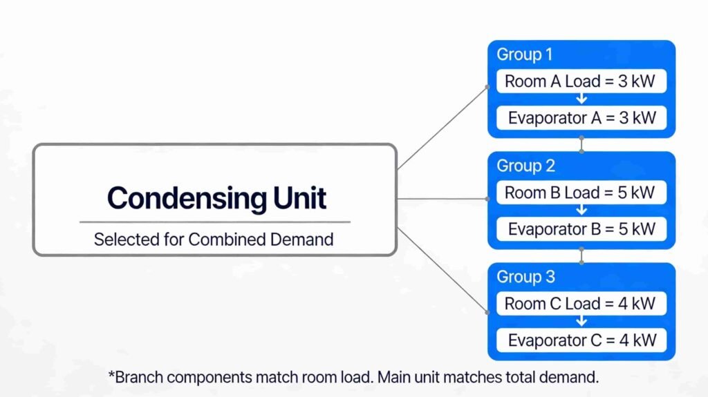
냉장실 냉각 분배
용량 분배 논리:
예를 들어:
샘플 로드 분석:
선정결과:
각 증발기는 자체 공간의 부하를 처리합니다.. 여러 방에서 동시에 냉각이 필요한 경우 응축 장치가 총 수요를 충족합니다..
즉:
-
너 그럴 필요는 없다 한 방에는 "30% 냉방"을 수동으로 할당하고 다른 방에는 "70%"를 수동으로 할당합니다..
-
각 지점의 크기를 올바르게 조정했습니다..
-
결합된 수요에 맞게 기본 장치의 크기를 조정합니다..
간단한 규칙 테이블
이 표는 기본적인 일대다 시스템이 작동하는 시기와 추가 제어가 필요한 시기를 고객이 이해하는 데 도움이 됩니다..
간단한 시스템을 사용해야 하는 경우와 압력 제어를 추가해야 하는 경우:
시스템을 단계별로 구성하는 방법
좋은 단일 응축 장치 다중 공간 설계는 일반적으로 이 프로세스를 따릅니다.:
단계 1: 기본 프로젝트 데이터 확인
단계 2: 각 방의 부하 계산
각 방을 별도로 계산해야 합니다..
주요 부하 품목:
이 단계에서는 각 방에 필요한 증발기 용량을 제공합니다..
단계 3: 각 방마다 하나의 증발기를 선택하십시오.
방의 부하와 작동 조건이 실제로 동일하지 않은 한 모든 증발기를 동일하게 만들지 마십시오..
단계 4: 결합 수요를 위한 응축 장치 선택
이 단계에서 많은 프로젝트가 잘못됩니다..
Some people size the 응축 장치 only by looking at one room. 이러한 접근 방식은 시작 중에 문제를 일으키는 경우가 많습니다., 과도한 사용, 또는 동시 냉각 수요.
응축 장치 선택 체크리스트:
응축 장치는 실제 작동 조건에서 시스템 요구 사항과 일치해야 합니다., 이상적인 실험실 조건뿐만 아니라.
단계 5: 냉매 배관 설계
다중 증발기 시스템은 전부하 및 부분부하 조건 모두에서 작동해야 하므로 우수한 배관 설계가 필요합니다..
배관 규칙:
오늘은 모든 방을 함께 냉각하면서 시스템을 실행할 수 있습니다., 그러면 오늘 밤에는 작은 방 하나만 냉방을 요청할 수 있습니다. 배관은 두 가지 조건을 모두 지원해야 합니다..
단계 6: 방별 제어 추가
독립적인 룸 제어는 멀티룸 시스템의 핵심입니다..
표준 제어 배열:
각 방은 자체 냉매 공급을 제어해야 합니다.. 그것 없이는, 한 방은 더 이상 냉각이 필요하지 않을 때 냉각을 계속할 수 있습니다..
단계 7: 펌프다운 제어 사용
펌프다운 제어로 압축기 보호.
펌프다운 시퀀스:
이 방법은 오프사이클 동안 액체 냉매 이동을 줄이는 데 도움이 됩니다..
단계 8: 각 방의 제상 계획
방마다 서리가 내리는 속도가 다른 경우가 많습니다..
제상 요인:
일반적으로 모든 증발기를 동시에 제상하는 것보다 제상 일정에 시차를 두는 것이 더 좋습니다..
예 1: 3개의 유사한 냉각실
이 예는 표준 동일 온도 프로젝트를 보여줍니다..
프로젝트 데이터:
실내 온도가 가깝기 때문에, 하나의 공유 응축 장치가 일반적으로 의미가 있습니다..
권장 구성:
운영 로직:
이러한 유형의 프로젝트는 단순성과 최상의 균형을 제공합니다., 비용, 안정적인 작동.
예 2: 냉각기 1개와 냉동고 1개
이 예는 혼합 온도 프로젝트를 보여줍니다..
프로젝트 데이터:
권장 구성:
운영 로직:
이 디자인은 잘 작동할 수 있습니다, 하지만 동일한 온도 시스템보다 더 나은 압력 제어와 더 세심한 설정이 필요합니다..
예 3: 에너지 소비량 비교
질문: “전기는 얼마나 쓸 수 있나요? 1 응축 장치는 작동 시 저장됩니다. 3 차가운 방, 사용하는 것과 비교 3 별도의 응축 장치?”
잘, 정해진 숫자는 없어.
위의 예와 같은 프로젝트의 경우: 하나의 응축 장치가 제공됩니다. 3 차가운 방 usually 약 절약 5% 에게 15% 전기 (인버터 콘덴서를 사용하면 대략적인 비용 절감이 가능합니다. 25% 에게 35%) 와 비교하다 3 실내 온도가 비슷한 경우 별도의 응축 장치 사용, 비슷한 영업시간, 그리고 좋은 배관 디자인.
간단한 답변:
하나의 장치로 전력을 절약할 수 있는 이유:
-
하나의 큰 응축 장치는 세 개의 작은 장치보다 더 효율적으로 작동하는 경우가 많습니다..
-
공유 시스템으로 사이클링 손실을 줄일 수 있습니다..
-
실내 부하가 변경될 때 하나의 시스템으로 용량을 보다 원활하게 사용할 수 있습니다..
그러나 저축은 사라질 수 있습니다:
쉬운 예:
만약에 3 별도의 단위 사용 100 kWh/일, 동일에 대한 하나의 공유 장치 3 비슷한 객실은 약 사용할 수 있습니다 85 에게 92 kWh/일.
알아채다: 실제 절감액은 실내 온도에 따라 달라집니다., 부하 다양성, 관, 및 제어 설계.
일반적인 실수
가장 일반적인 설계 오류:
결론
실내 온도가 일치하면 하나의 응축 장치로 여러 개의 냉장실을 원활하게 운영할 수 있습니다., 각 증발기의 크기를 올바르게 지정하십시오., 제어 장치와 배관을 주의 깊게 설계하십시오..
혼합 온도 프로젝트용, 올바른 압력 컨트롤 추가, EPR과 같은, 실내 안정성과 제품 품질을 보호하기 위해. 잘 계획된 일대다 시스템으로 비용을 절감할 수 있습니다., 공간 절약, 안정적인 성능을 제공합니다..