Using one condensing unit for multiple cold rooms means one outdoor unità di condensazione supplies refrigerant to two or more evaporators, solitamente un evaporatore per ogni stanza, attraverso una linea del liquido condivisa e un ritorno di aspirazione condiviso.
Questa configurazione può ridurre i costi delle apparecchiature, risparmiare spazio esterno, e semplificare la manutenzione. Tuttavia, funziona bene solo quando la temperatura ambiente, condizioni di carico, progettazione delle tubazioni, e la logica di controllo corrispondono all'applicazione.
L'idea chiave è semplice: each stanza fredda must cool independently.
Una stanza dovrebbe richiedere il raffreddamento, raggiungere la temperatura impostata, e interrompere il raffreddamento senza forzare il raffreddamento eccessivo delle altre stanze o perdere il controllo.
Quando questo progetto ha senso
A one-condensing-unit multi-room design works best when the stanze fredde have similar temperatures and similar operating conditions.
Buone applicazioni:
| Tipo di progetto | Idoneità | Perché |
|---|---|---|
| Due o più stanze frigorifere | Bene | Temperature ambiente simili facilitano il controllo |
| Due o più celle frigorifere | Di solito buono | La stessa condizione di aspirazione funziona meglio |
| Diverse piccole celle frigorifere in un'unica struttura | Bene | Risparmia spazio e riduce la quantità di attrezzature |
| Progetti con area di installazione esterna limitata | Bene | Un'unità condensante necessita di meno spazio |
Applicazioni che necessitano di cure extra:
Se tutte le stanze mantengono una temperatura simile, una condizione di aspirazione condivisa può spesso supportare l'intero sistema. Se una stanza funziona come congelatore e un'altra come refrigeratore, il progetto necessita di un ulteriore controllo della pressione.
Come funziona il sistema
In questo disegno, IL unità di condensazione acts as the refrigeration source, e ciascuna cella frigorifera funge da zona di raffreddamento indipendente.
Ogni stanza solitamente include i propri componenti di controllo e di alimentazione del refrigerante.
Disposizione dei componenti di base:
Il termostato in ogni stanza controlla l'elettrovalvola di quella stanza.
Quando la temperatura ambiente supera il setpoint, il termostato apre l'elettrovalvola. Il refrigerante fluisce quindi verso l'evaporatore di quella stanza. Quando la stanza raggiunge il setpoint, il termostato chiude l'elettrovalvola e interrompe il flusso di refrigerante in quella stanza.
Questa configurazione offre a ciascuna stanza un controllo di attivazione/disattivazione del raffreddamento indipendente mentre tutte le stanze condividono un'unità di condensazione.
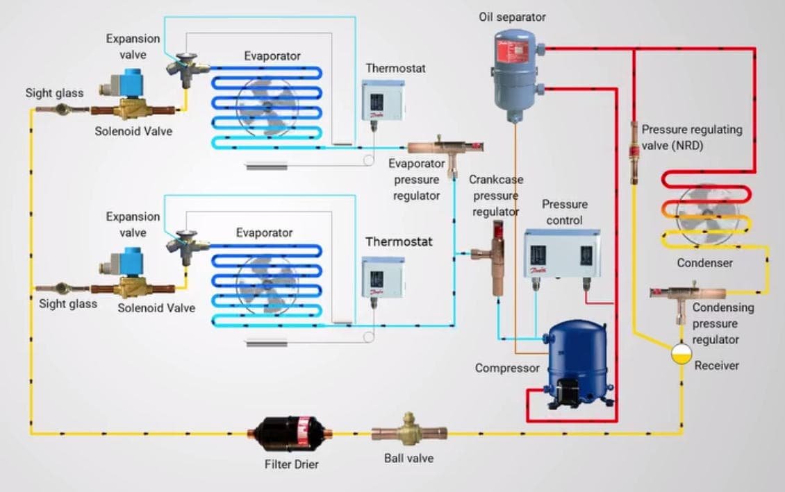
Circuito di refrigerazione di più celle frigorifere
Camere a stessa temperatura: La configurazione più semplice
Le stanze con la stessa temperatura creano la configurazione uno-a-molti più semplice e affidabile.
Per esempio, if you have three stanze fredde at +2°C, +3°C, e +4°C, un'unità di condensazione condivisa spesso funziona bene perché il sistema può utilizzare una condizione di aspirazione simile per tutte e tre le stanze.

Layout del sistema alla stessa temperatura:
Perché questo layout funziona bene:
In questo tipo di progetto, il sistema di solito controlla bene i calcoli del carico, tubazioni, e la selezione dei componenti siano corretti.
Camere a temperatura mista: Chiller e congelatore in un'unica unità
When one unità di condensazione serves a chiller and a freezer, la progettazione diventa più difficile.
Il motivo è: il congelatore necessita di una pressione di aspirazione inferiore.
Se il refrigeratore condivide direttamente la stessa condizione di bassa aspirazione, l'evaporatore del refrigeratore può diventare troppo freddo. Ciò può causare un raffreddamento eccessivo, glassa a spirale, temperatura ambiente instabile, o addirittura il congelamento del prodotto all'interno del refrigeratore.

Esempio:
In questa situazione, un sistema condiviso di base di solito non funziona bene da solo.
La filiale della sala refrigerata spesso necessita di un Valvola EPR.
Cosa fa una valvola EPR
Una valvola EPR aiuta la stanza più calda a mantenere una pressione dell'evaporatore più elevata.
Di solito si installa la valvola EPR nella linea di aspirazione della stanza più calda, dopo l'evaporatore e prima del collettore di aspirazione comune.
Logica della valvola EPR:
Con questa disposizione:
-
Il ramo congelatore segue la condizione di minore aspirazione di cui necessita.
-
Il ramo del refrigeratore rimane a una pressione dell'evaporatore più elevata perché la valvola EPR la mantiene lì.
In questo modo un'unità condensatrice può servire in modo più sicuro due ambienti a temperature diverse.
Quando è opportuno utilizzare una valvola EPR
- Se la differenza di temperatura ambiente rimane entro 5°C, di solito un'unità condensante funziona bene per entrambe le stanze. Il controllo rimane più semplice e il sistema funziona in modo più stabile. Non è necessaria la valvola EPR.
- Se la differenza di temperatura supera gli 8°C ~ 10°C, non posso trattarlo come una semplice configurazione di unità condivisa. Di solito è necessario valutare il sistema e aggiungere una valvola EPR, soprattutto per una combinazione refrigeratore-congelatore.
Per esempio: una cella frigorifera a +5°C e una cella congelatore a -18°C hanno un ampio intervallo di temperature, quindi di solito dovresti aggiungere una valvola EPR. Altrimenti, il ramo del refrigeratore può diventare troppo freddo.
Quando una valvola CPR può essere d'aiuto
Alcuni progetti necessitano anche di a Valvola RCP vicino all'aspirazione del compressore.
Una valvola CPR protegge il compressore durante l'avvio o il pull-down a caldo. Se più stanze richiedono il raffreddamento contemporaneamente, o se nelle stanze entra prodotto caldo, la pressione di aspirazione può aumentare rapidamente. Una pressione di aspirazione elevata può sovraccaricare il compressore.
Logica della valvola RCP:
| Domanda | Risposta |
|---|---|
| Perché utilizzare una valvola CPR? | Proteggere il compressore in condizioni di carico pesante |
| Dove lo installi? | Vicino all'aspirazione del compressore |
| Quando è utile? | Abbattimento caldo, carico di avvio pesante, apertura frequente della porta |
| Ogni progetto ne ha bisogno? | NO, ma alcuni progetti a carico misto o pesante lo fanno |
Come viene distribuita la capacità di raffreddamento
Questa è una delle domande più comuni dei clienti:
If one unità di condensazione serves several rooms, come il sistema divide la capacità di raffreddamento?
La risposta breve è: il sistema non divide il raffreddamento in base a congetture. La corretta selezione dei componenti determina il modo in cui il sistema distribuisce il raffreddamento.
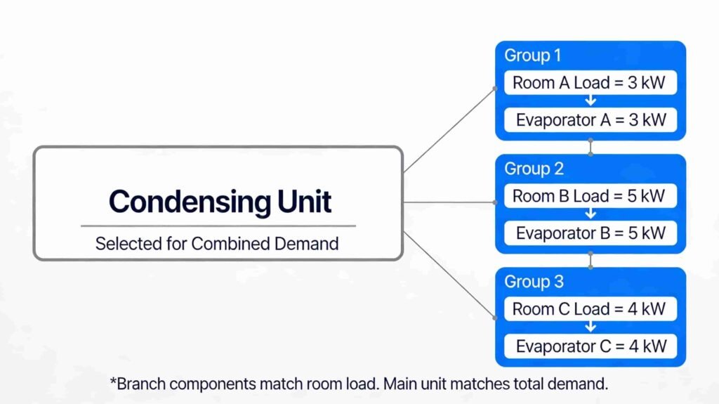
Distribuzione del raffreddamento delle celle frigorifere
Logica di distribuzione della capacità:
Per esempio:
Esempio di ripartizione del carico:
Risultato della selezione:
Ogni evaporatore gestisce il carico del proprio ambiente. L'unità condensante copre la domanda totale quando più stanze richiedono il raffreddamento contemporaneamente.
Ciò significa:
-
Voi non è necessario assegnare manualmente il “30% di raffreddamento” a una stanza e il “70%” a un'altra stanza.
-
Dimensiona correttamente ciascun ramo.
-
Si dimensiona l'unità principale per la domanda combinata.
Tabella delle regole semplici
Questa tabella aiuta i clienti a capire quando funziona un sistema uno-a-molti di base e quando necessita di controlli aggiuntivi.
Quando utilizzare un sistema semplice e quando aggiungere il controllo della pressione:
Come configurare il sistema passo dopo passo
Un buon progetto multi-room con una sola unità di condensazione di solito segue questo processo:
Fare un passo 1: Conferma i dati del progetto di base
Fare un passo 2: Calcolare il carico per ogni stanza
Dovresti calcolare ogni stanza separatamente.
Elementi di carico principali:
Questo passaggio ti fornisce la capacità dell'evaporatore richiesta per ogni stanza.
Fare un passo 3: Seleziona un evaporatore per ogni stanza
Non rendere tutti gli evaporatori uguali a meno che le stanze non abbiano veramente lo stesso carico e le stesse condizioni operative.
Fare un passo 4: Seleziona l'unità di condensazione per la domanda combinata
Questo passaggio è dove molti progetti vanno male.
Some people size the unità di condensazione only by looking at one room. Questo approccio spesso crea problemi durante l'avvio, uso pesante, o richiesta di raffreddamento simultanea.
Lista di controllo per la selezione dell'unità di condensazione:
L'unità condensante deve soddisfare la domanda del sistema in condizioni operative reali, non solo condizioni di laboratorio ideali.
Fare un passo 5: Progettare le tubazioni del refrigerante
Un sistema multi-evaporatore necessita di una buona progettazione delle tubazioni perché deve funzionare sia in condizioni di carico pieno che parziale.
Regole sulle tubazioni:
Oggi un sistema può funzionare con il raffreddamento di tutte le stanze insieme, allora solo una piccola stanza potrebbe richiedere un raffreddamento stasera. Le tubazioni devono supportare entrambe le condizioni.
Fare un passo 6: Aggiungi controlli stanza per stanza
Il controllo indipendente della stanza è il cuore di un sistema multi-room.
Disposizione di controllo standard:
Ogni stanza dovrebbe controllare la propria alimentazione di refrigerante. Senza quello, una stanza può continuare a raffreddarsi quando non ne ha più bisogno.
Fare un passo 7: Utilizzare il controllo dello svuotamento
Il controllo del pump-down aiuta a proteggere il compressore.
Sequenza di svuotamento:
Questo metodo aiuta a ridurre la migrazione del refrigerante liquido durante i cicli di inattività.
Fare un passo 8: Pianifica lo sbrinamento per ogni stanza
Stanze diverse spesso accumulano brina a velocità diverse.
Fattori di scongelamento:
Di solito è meglio scaglionare i programmi di sbrinamento invece di sbrinare tutti gli evaporatori contemporaneamente.
Esempio 1: Tre sale refrigerate simili
Questo esempio mostra un progetto standard con la stessa temperatura.
Dati del progetto:
Perché le temperature della stanza sono vicine, di solito ha senso avere un'unità di condensazione condivisa.
Configurazione consigliata:
Logica operativa:
Questo tipo di progetto offre il miglior equilibrio di semplicità, costo, e funzionamento stabile.
Esempio 2: Un refrigeratore e un congelatore
Questo esempio mostra un progetto a temperatura mista.
Dati del progetto:
Configurazione consigliata:
Logica operativa:
Questo design può funzionare bene, ma necessita di un migliore controllo della pressione e di una configurazione più attenta rispetto a un sistema alla stessa temperatura.
Esempio 3: Confronto del consumo energetico
Domanda: “Quanta elettricità può 1 unità condensatrice salva quando serve 3 stanze fredde, rispetto all'utilizzo 3 unità condensatrici separate?"
BENE, non c'è un numero fisso.
Per un progetto come l'esempio sopra: serve un'unità condensatrice 3 stanze fredde usually risparmia circa 5% A 15% elettricità (se si utilizza un'unità condensante con inverter è possibile risparmiare circa 25% A 35%) rispetto a 3 unità condensatrici separate quando gli ambienti hanno temperature simili, orari di funzionamento simili, e un buon design delle tubazioni.
Risposta semplice:
Perché un'unità può risparmiare energia:
-
Un'unità di condensazione più grande spesso funziona in modo più efficiente di tre unità piccole.
-
Un sistema condiviso può ridurre le perdite dovute al ciclismo.
-
Un sistema può utilizzare la capacità in modo più fluido quando cambiano i carichi della stanza.
Ma i risparmi possono scomparire:
Esempio facile:
Se 3 utilizzo di unità separate 100 kWh/giorno, una unità condivisa per lo stesso 3 stanze simili possono essere utilizzate circa 85 A 92 kWh/giorno.
AVVISO: Il risparmio effettivo dipende dalla temperatura ambiente, diversità di carico, tubazioni, e progettazione del controllo.
Errori comuni
Errori di progettazione più comuni:
Conclusione
Un'unità di condensazione può gestire bene più celle frigorifere quando si abbinano le temperature ambiente, dimensionare correttamente ciascun evaporatore, e progettare con cura i controlli e le tubazioni.
Per progetti a temperatura mista, aggiungere i giusti controlli di pressione, come l'EPR, per proteggere la stabilità della stanza e la qualità del prodotto. Un sistema uno-a-molti ben pianificato può ridurre i costi, risparmiare spazio, e fornire prestazioni affidabili.