最適なソリューションを共有する, HVACR の専門知識と業界ニュース

単一の凝縮ユニットで複数の冷蔵室を稼働させる方法?

目次

Using one condensing unit for multiple cold rooms means one outdoor condensing unit supplies refrigerant to two or more evaporators, usually one evaporator for each room, through a shared liquid line and a shared suction return.

This setup can lower equipment cost, save outdoor space, and simplify maintenance. しかし, it only works well when the room temperatures, load conditions, piping design, and control logic all match the application.
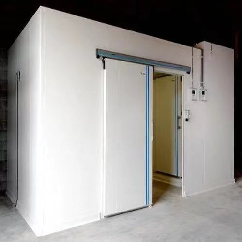
The key idea is simple: each cold room must cool independently.

One room should call for cooling, reach set temp, and stop cooling without forcing the other rooms to overcool or lose control.

When This Design Makes Sense

A one-condensing-unit multi-room design works best when the cold rooms have similar temperatures and similar operating conditions.

Good Applications:

Project Type Suitability なぜ
Two or more chiller rooms Good Similar room temperatures make control easier
Two or more freezer rooms Usually good Same suction condition works better
Several small cold rooms in one facility Good Saves space and reduces equipment quantity
Projects with limited outdoor installation area Good One condensing unit needs less space

Applications That Need Extra Care:

Project Type Risk Level Main Concern
One chiller + one freezer 高い The chiller room may run too cold
Large difference in room temperatures 高い One suction pressure doesn’t suit all rooms
Critical storage with backup requirement 高い One condensing unit becomes a single point of failure
Long piping runs with vertical risers Medium to high Oil return and pressure drop need close attention

If all rooms stay close in temperature, one shared suction condition can often support the whole system. If one room runs as a freezer and another runs as a chiller, the design needs extra pressure control.

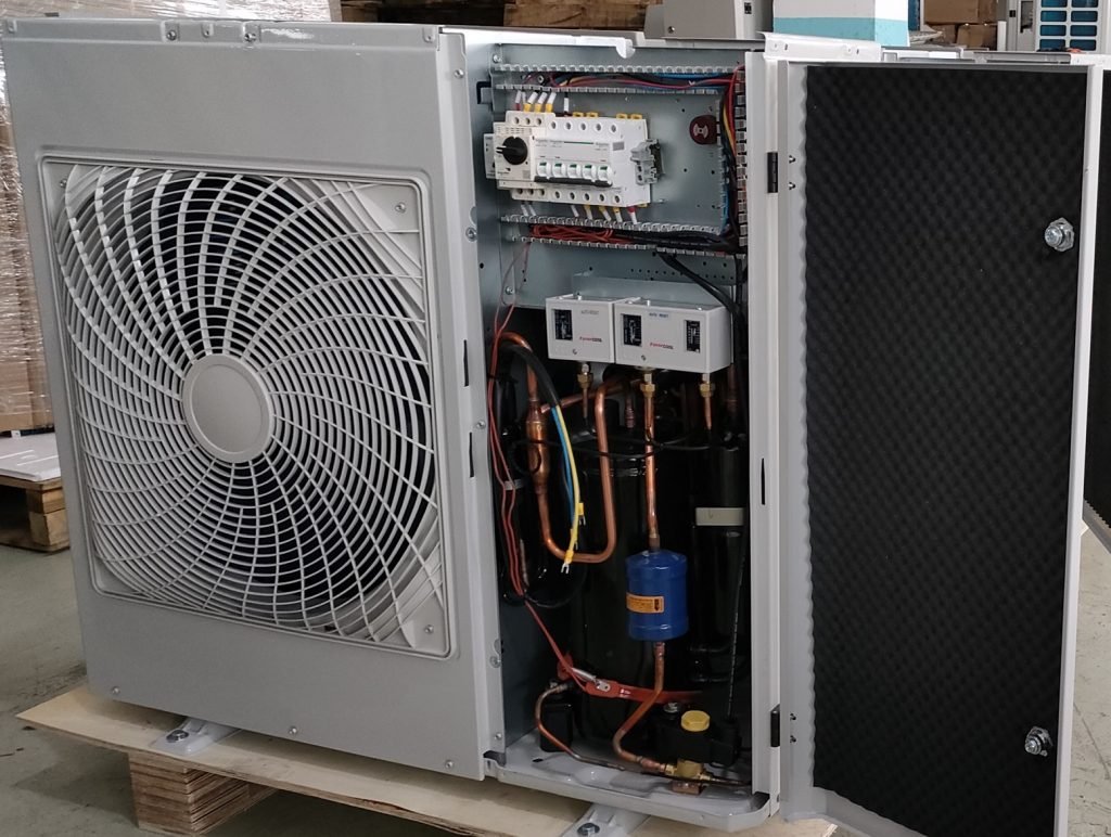
How the System Works

In this design, the condensing unit acts as the refrigeration source, and each cold room acts as an independent cooling zone.

Each room usually includes its own control and refrigerant feed components.

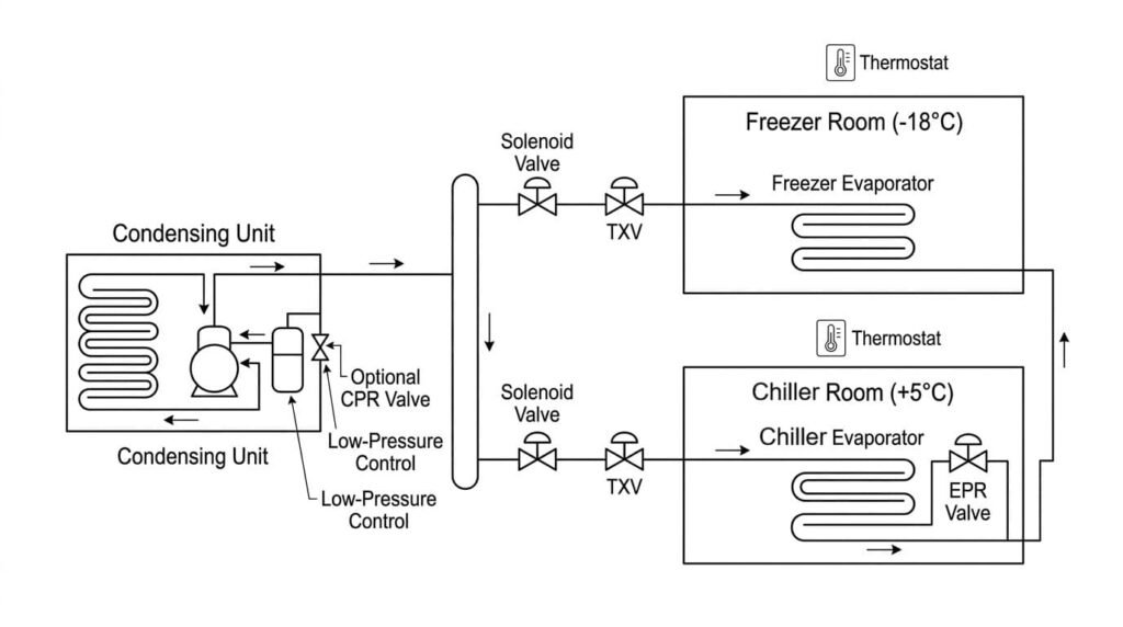
Basic Component Layout:

成分 Quantity Rule 関数
Condensing unit 1 for the system Provides total refrigeration capacity
蒸発器 1 per room Removes heat from that room
Thermostat or room controller 1 per room Starts or stops cooling for that room
Liquid line solenoid valve 1 per room Opens or closes refrigerant flow
Expansion valve (TXV/TEV) 1 per evaporator Feeds refrigerant into the evaporator correctly
Liquid header 1 main header Splits liquid refrigerant to each branch
Suction header 1 main header Collects suction gas from all branches
Low-pressure control 1 main control Stops the compressor during pump-down

The thermostat in each room controls that room’s solenoid valve.

When the room temperature rises above setpoint, the thermostat opens the solenoid valve. Refrigerant then flows to that room’s evaporator. When the room reaches setpoint, the thermostat closes the solenoid valve and stops refrigerant flow to that room.

This setup gives each room independent on/off cooling control while all rooms share one condensing unit.

Multiple Cold Rooms With Single Condensing unit

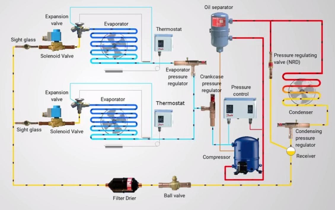
Multiple Cold Rooms Refrigeration Circuit

Same-Temperature Rooms: The Simplest Configuration

Same-temperature rooms create the simplest and most reliable one-to-many setup.

例えば, if you have three cold rooms at +2°C, +3℃, and +4°C, one shared condensing unit often works well because the system can use a similar suction condition for all three rooms.

System Working Principle-3 same temp cold room

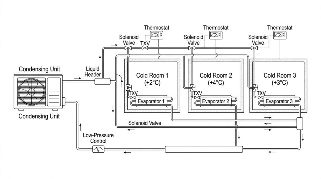
Same-Temperature System Layout:

Section 構成
Refrigerant supply One liquid line from the condensing unit to one liquid header
Room branches One branch from the liquid header to each room
Room control One thermostat and one solenoid valve for each room
Refrigerant feed One TXV for each evaporator
Return gas One suction branch from each evaporator to one suction header
Compressor stop Pump-down with low-pressure control

Why This Layout Works Well:

理由 Explanation
Similar room temperatures One shared suction condition can satisfy all rooms
Simple controls Each room only needs thermostat + solenoid + TXV
Lower equipment cost One condensing unit replaces several separate units
Easier installation Fewer outdoor units and less electrical work

In this type of project, the system usually controls well as long as the load calculations, piping, and component selection are correct.

Mixed-Temperature Rooms: Chiller and Freezer on One Unit

When one condensing unit serves a chiller and a freezer, the design becomes more difficult.

The reason is: the freezer needs a lower suction pressure.

If the chiller shares that same low suction condition directly, the chiller evaporator can run too cold. That can cause overcooling, coil icing, unstable room temperature, or even product freezing inside the chiller.

System Working Principle-1 freezer 1 チラー

Example:

Room Target Temperature チャレンジ
Chiller room +5℃ Needs a higher evaporating temperature
フリーザールーム -18℃ Needs a much lower suction condition

この状況では, a basic shared system usually doesn’t perform well by itself.

The chiller room branch often needs an EPR valve.

What an EPR Valve Does

An EPR valve helps the warmer room keep a higher evaporator pressure.

You usually install the EPR valve in the suction line of the warmer room, after the evaporator and before the common suction header.

EPR Valve Logic:

質問 答え
Why use an EPR valve? It keeps the warmer room from running too cold
Which room usually needs it? The warmer room branch
Where do you install it? On the suction outlet of the warmer room evaporator
What does it control? Minimize evaporator pressure on that branch
What problem does it prevent? Overcooling and unstable control in the warmer room

With this arrangement:

  • The freezer branch follows the lower suction condition it needs.

  • The chiller branch stays at a higher evaporator pressure because the EPR valve holds it there.

That is how one condensing unit can serve two different temperature rooms more safely.

When should use a EPR Valve

  • If the room temperature difference stays within 5°C, one condensing unit usually works well for both rooms. Control stays simpler and the system runs more steadily. No need EPR valve.
  • If the temperature difference goes beyond 8°C ~ 10°C, can’t treat it as a simple shared-unit setup. You usually need to evaluate the system and add an EPR valve, especially for a chiller-plus-freezer combination.

例えば: a +5°C chiller room and a -18°C freezer room have a large temperature gap, so you should usually add an EPR valve. さもないと, the chiller branch can run too cold.

When a CPR Valve May Help

Some projects also need a CPR valve near the compressor suction.

A CPR valve protects the compressor during startup or hot pull-down. If several rooms call for cooling at the same time, or if warm product enters the rooms, suction pressure can rise quickly. That high suction pressure can overload the compressor.

CPR Valve Logic:

質問 答え
Why use a CPR valve? Protect compressor during heavy load conditions
Where do you install it? Near the compressor suction
When is it useful? Hot pull-down, heavy startup load, frequent door opening
Does every project need it? いいえ, but some mixed-load or heavy-load projects do

How Cooling Capacity Is Distributed

This is one of the most common questions from customers:

If one condensing unit serves several rooms, how does the system divide the cooling capacity?

The short answer is: the system doesn’t divide cooling by guesswork. Proper component selection determines how the system distributes cooling.

Cold Room Cooling Distribution 1

Cold Room Cooling Distribution

Capacity Distribution Logic:
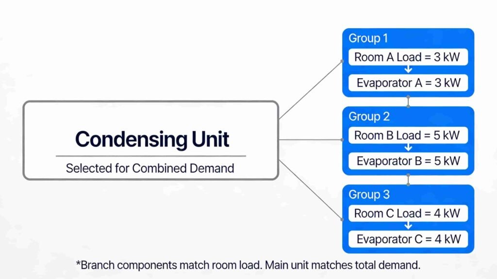
System Part Selection Rule
Each cold room Calculate its own heat load
Each evaporator Match that room’s load and room temperature
Each TXV Match that evaporator and refrigerant
Main condensing unit Match the realistic combined demand

例えば:

Sample Load Breakdown:

Room 室温 Estimated Load
Room A +4℃ 3 KW
Room B +2℃ 5 KW
Room C +3℃ 4 KW

Selection Result:

成分 Selection Basis Example
Evaporator A Room A load だいたい 3 KW
Evaporator B Room B load だいたい 5 KW
Evaporator C Room C load だいたい 4 KW
Condensing unit Combined operating demand だいたい 12 kW total demand

Each evaporator handles the load of its own room. The condensing unit covers the total demand when multiple rooms call for cooling at the same time.

That means:

  • You needn’t manually assign “30% cooling” to one room and “70%” to another room.

  • You size each branch correctly.

  • You size the main unit for the combined demand.

Simple Rule Table

This table helps customers understand when a basic one-to-many system works and when it needs extra controls.

When to Use a Simple System and When to Add Pressure Control:

Project Type Temperature Difference Basic Shared System EPR Valve CPR Valve Recommendation
Two or more chiller rooms 小さい はい Usually no Usually no Good fit
Two or more freezer rooms 小さい はい Usually no 時々 Usually workable
One chiller + one freezer 大きい いいえ Usually yes 時々 Needs careful design
Critical storage with backup needs Any Possible but risky Depends Depends Separate systems often make more sense

How to Configure the System Step by Step

A good one-condensing-unit multi-room design usually follows this process:

ステップ 1: Confirm Basic Project Data

Item to Confirm なぜそれが重要なのか
Number of rooms Defines branch quantity
Room temperatures Decides whether rooms can share one suction condition
Product type Affects humidity, airflow, and defrost needs
Room sizes Supports load calculation
Pipe distance Affects pipe sizing and pressure drop
周囲温度 Affects condensing unit capacity
Refrigerant type Affects valve selection and line sizing

ステップ 2: Calculate the Load for Each Room

You should calculate each room separately.

Main Load Items:

Load Type 説明
Transmission load Heat gain through walls, シーリング, そして床
Product load Heat removed from stored products
Infiltration load Warm air entering through door opening
Internal load 点灯, people, fan motors
Pull-down load Extra load when warm product enters the room

This step gives you the required evaporator capacity for each room.

ステップ 3: Select One Evaporator for Each Room

Selection Item なぜそれが重要なのか
室温 Changes coil operating condition
Heat load Determines required capacity
気流 Affects room temperature uniformity
Product sensitivity Some products need gentler air movement or better humidity control
Defrost method Affects coil operation and control logic

Don’t make all evaporators the same unless the rooms truly have the same load and same operating conditions.

ステップ 4: Select the Condensing Unit for Combined Demand

This step is where many projects go wrong.

Some people size the condensing unit only by looking at one room. That approach often creates trouble during startup, heavy use, or simultaneous cooling demand.

Condensing Unit Selection Checklist:

Selection Factor What to Check
Combined room load Total demand when several rooms cool together
Simultaneous running condition Worst realistic operating case
SST / evaporating condition Must match the application
周囲温度 Must match local installation climate
Unit operating limitation Must stay within manufacturer limits

The condensing unit must match the system demand under real operating conditions, not just ideal lab conditions.

ステップ 5: Design the Refrigerant Piping

A multi-evaporator system needs good piping design because it must work in both full-load and part-load conditions.

Piping Rules:

Piping Item Good Practice
Branch liquid lines Size them for each evaporator load
Main liquid header Size it for total possible flow
Branch suction lines Size them for each evaporator return flow
Main suction header Size it for combined return flow
Vertical risers Check oil return carefully
Suction line insulation Always protect against heat gain and condensation
Pressure drop Keep it within a reasonable range

A system may run with all rooms cooling together today, then only one small room may call for cooling tonight. Your piping must support both conditions.

ステップ 6: Add Room-by-Room Controls

Independent room control is the heart of a multi-room system.

Standard Control Arrangement:

Room Component 関数
サーモスタット / controller Detects room temperature
Solenoid valve Starts or stops refrigerant flow
TXV Feeds the evaporator
ファン / defrost control Supports room operation

Each room should control its own refrigerant feed. Without that, one room can keep cooling when it no longer needs cooling.

ステップ 7: Use Pump-Down Control

Pump-down control helps protect the compressor.

Pump-Down Sequence:

Sequence What Happens
1 Room reaches setpoint
2 Thermostat closes that room’s solenoid valve
3 Refrigerant feed stops to that evaporator
4 Compressor continues running briefly
5 Suction pressure falls
6 Low-pressure control stops the compressor

This method helps reduce liquid refrigerant migration during off cycles.

ステップ 8: Plan Defrost for Each Room

Different rooms often build frost at different rates.

Defrost Factors:

Factor Effect
Room humidity Higher humidity creates more frost
Door traffic Frequent opening increases frost load
室温 Lower evaporator temperatures increase frosting risk
Product moisture Moist products can add humidity to the room

It is usually better to stagger defrost schedules instead of defrosting all evaporators at the same time.

Example 1: Three Similar Chiller Rooms

This example shows a standard same-temperature project.

Project Data:

アイテム Room 1 Room 2 Room 3
応用 Vegetables Beverages 乳製品
室温 +4℃ +2℃ +3℃
Estimated Room Load 3 KW 5 KW 4 KW
Control Type サーモスタット + Solenoid サーモスタット + Solenoid サーモスタット + Solenoid

Because the room temperatures are close, one shared condensing unit usually makes sense.

成分 ノート
Condensing unit 1 Sized for combined demand
蒸発器 3 One per room
サーモスタット / room controller 3 One per room
Solenoid valve 3 One per room
TXV 3 One per evaporator
Liquid header 1 Shared
Suction header 1 Shared
Low-pressure control 1 For pump-down

Operating Logic:

Operating Condition System Response
Only Room 1 calls Solenoid 1 opens, only Room 1 cools
Room 1 and Room 2 call Both branches run
All rooms call Condensing unit handles combined demand
One room reaches setpoint That room’s solenoid closes
All rooms reach setpoint Pump-down stops the compressor

This type of project gives the best balance of simplicity, 料金, and stable operation.

Example 2: One Chiller and One Freezer

This example shows a mixed-temperature project.

Project Data:

アイテム Chiller Room Freezer Room
室温 +5℃ -18℃
Estimated Room Load 4 KW 9 KW
Basic Control サーモスタット + Solenoid サーモスタット + Solenoid
Extra Pressure Control EPR required Usually not required on this branch
成分 Chiller Room Freezer Room
サーモスタット はい はい
Solenoid valve はい はい
TXV はい はい
蒸発器 はい はい
EPR valve はい いいえ
Shared condensing unit はい はい

Operating Logic:

Operating Condition System Response
Freezer calls System follows low suction condition
Chiller calls Chiller branch opens
Both rooms call Freezer runs low, chiller branch stays protected by EPR
Heavy startup load CPR may protect the compressor if required

This design can work well, but it needs better pressure control and more careful setup than a same-temperature system.

Example 3: Energy Consumption Comparison

質問: “How much electricity can 1 condensing unit save when it serves 3 寒い部屋, compared with using 3 separate condensing units?」

良い, there is no fixed number.

For a project like the example above: one condensing unit serves 3 cold rooms usually saves about 5% に 15% 電気 (if you use inverter condensing unit can save roughly 25% に 35%) compared with 3 separate condensing units when the rooms have similar temperatures, similar operating hours, and good piping design.

Simple answer:

Setup Typical power result
1 condensing unit for 3 similar cold rooms Usually lower total power use
3 separate condensing units Usually higher total power use

Why one unit can save power:

  • One larger condensing unit often runs more efficiently than three small units.

  • A shared system can reduce cycling losses.

  • One system can use capacity more smoothly when room loads change.

But savings can disappear:

Situation Result
Rooms have very different temperatures Savings may drop or disappear
Poor piping or wrong controls Power use can increase
Long pipe runs or bad oil return Efficiency can drop

Easy example:

If 3 separate units use 100 kWh/day, one shared unit for the same 3 similar rooms may use about 85 に 92 kWh/day.

知らせ: Actual savings depend on room temperature, load diversity, piping, and control design.

Common Mistakes

Most Common Design Errors:

Mistake What Goes Wrong
Mixing chiller and freezer without EPR Chiller room runs too cold
No solenoid valve for each room Independent control becomes poor
Wrong pipe sizing Pressure drop or oil return problems appear
Undersized condensing unit System struggles during simultaneous load
Poor defrost planning Rooms warm up too much or system becomes unstable
Ignore compressor protection Startup or pull-down may overload the compressor

Need Help With a Multi-Room Cold Room Project?

Send us the following project details, and we can suggest you a suitable solution.

What to Send Us:

Information Why We Need It
Number of cold rooms To plan the system layout
Room temperatures To check temperature compatibility
Room sizes or loads To size evaporators and condensing unit
Refrigerant type To match the valves and system design
Pipe distance To check line sizing and pressure drop
周囲温度 To confirm condensing unit capacity
Product type To review humidity and defrost needs

注意: Send us your project details, and we can suggest a suitable one-condensing-unit solution with recommended controls, piping logic, and component arrangement.

結論

One condensing unit can run multiple cold rooms well when you match room temperatures, size each evaporator correctly, and design the controls and piping with care.

For mixed-temperature projects, add the right pressure controls, such as EPR, to protect room stability and product quality. A well-planned one-to-many system can lower cost, スペースを節約, and deliver reliable performance.

コメント?

ようこそメッセージを残すか、再投稿してください.

フェイスブック
ツイッター
リンクトイン
レディット
印刷する
の写真 ビック・チャン
ビック・チャン

やあ, 私はヴィックです! 以来、HVACR分野での作業を開始 2008, 当社の主力製品が含まれます: 空調, 冷蔵室冷凍システム, ウォーターチラー, 氷製造機, 業務用脱水機, 除湿機, ヒートポンプ, 電気モーター, とすべての付属品. 中国スピードウェイグループに参加して以来 2012, 私はここで以上の仕事をしました 10 年, 輸出部門の部長として, 私たちは確立しました 50+ さまざまな国や地域の代理店.
私たちの経験と強力な技術サポートとして, 問題が発生したら、問題を解決できます, 当社のチーフエンジニアは以来、HVACR分野で働いています。 1997. エンジニアだけでなく、私たちの知識がますます人気になっていることを誇りに思います, HVACR ビジネスの新規参入者向け, DIY愛好家. 私たちの記事を楽しんでいただければ幸いです, 質問やコメントがあれば、cn-beyond.com でマーケティングを送ってください。

すべての投稿

返信を残す

当社について

チャイナ・スピードウェイ・グループ プロフェッショナルな HVACR 製品です’ メーカーと卸売業者, さまざまな HVACR 製品およびスペアパーツをカスタマイズします, 特に冷凍製品と部品. エアコンなど, 冷凍装置, 冷蔵室ユニット, 氷製造機, 除湿機, 電気モーター, アクセサリー (コンプレッサー, 熱交換器, 銅コイル, バルブ, コントロールボックス, 蒸発器) 等.

以来、HVACR分野で働いてきました 2010, 私たちはより多くの経験を持っており、独自の製品とソリューションを提供できます, また、生涯無料の技術サポートを提供します. あなたのサンプルでお問い合わせを歓迎します, 描画またはデザイン, 私たちの目的は、あなたのアイデアを実現し、あなたに利益をもたらすことです.

そのうえ, 私たちのクライアントのために, 他の製品を調達します, サプライヤーを確認する, あなたのための無料料金で彼らと交渉する.

の写真 ビック・チャン
ビック・チャン

私はこの記事の著者です, そしてゼネラルマネージャー兼マーケティングディレクターでもあります。 "中国スピードウェイ", と 15+ HVACR業界での長年の経験. ご質問がございましたら, いつでも私に連絡できます.

著者についてさらに詳しく

お問い合わせ

メールアドレスを入力するだけです, 電話番号とこのフォームでのお問い合わせの簡単な説明. 以内にご連絡させていただきます 24 時間.

お問い合わせ

私たちと一緒にプロジェクトを始める準備ができました?

私たちと提携してブランドの評判を高めてください, クライアントにあなたのことを一生覚えてもらえるような印象的な体験を提供します, 競争市場で目立つように支援します !

最高の OEM パートナーをお見逃しなく!

私たちと一緒に働く準備ができています?

私たちの違いを体験し、あなたのビジネスのより良い未来に向けた第一歩を踏み出しましょう!